
10 led VU Meter using LM3915
The described circuit operates on a principle of visual signal representation using a VU meter configuration. The core component, the LM3915, is a dot/bar graph display driver that can illuminate up to 10 LEDs in response to an input voltage. This IC is particularly suited for audio level indication, providing a clear visual representation of signal strength.
The circuit begins with the input signal, which is fed into the TL071 operational amplifier. This op-amp is configured for half-wave rectification, ensuring that only the positive half of the input waveform is processed. This rectified output is then fed into the LM3915, which interprets the voltage level and activates the corresponding number of LEDs based on the input signal strength.
The switch S1 introduces versatility to the circuit by allowing users to select different voltage ranges for indication. This feature is essential for applications where varying signal levels need to be monitored. The circuit can effectively display levels from as low as 60 mV, suitable for low-level audio signals, up to 25 V, accommodating higher voltage signals.
In terms of component selection, the TL071 is favored for its low noise and high precision, making it ideal for audio applications. The LM3915's ability to drive multiple LEDs without additional components simplifies the design and reduces potential points of failure.
Overall, this circuit design provides a reliable and visually intuitive method for monitoring signal levels, making it suitable for various electronic applications, including audio equipment, signal processing, and general voltage level monitoring.Circuit diagram is a very simple circuit-level indication, with 10 Led. Used a series of half-wave rectification of precision around IC2 TL071, with a single. LM3915 IC is used to control the led, as an indicator VU Meter. LM3915 can be controlled 10 led. With the switch S1, we can choose an indication from the LED. Level mV into a 60-1st, 25 V. T he following is a schematic drawing: 🔗 External reference
Related Circuits
This circuit operates two LED strips in pulsing mode, where one LED strip transitions from an off state to gradually lighting up, then dimming, while the other LED strip performs the opposite action. Each strip can consist of 2...
A keyed power input connector, series rectifier and a shunt rectifier, both 1N4007, prevent reverse voltage from being applied to the power input. A 27 volt metal oxide varistor clamps the voltage to the 78L05 that follow it, to...
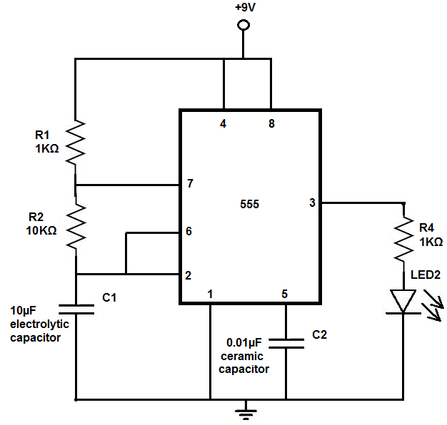
The 555 timer chip is a versatile integrated circuit (IC) that, when connected correctly, can generate pulses of current at specific intervals determined by a resistor-capacitor (RC) network. In this mode, the LED does not remain constantly lit; it...

This simple LED light flasher project utilizes a Hex Inverter 74C04 integrated circuit (IC) to generate a square wave pulse, which is employed to alternately turn two LEDs on and off. The circuit design comprises a 74C04 Hex Inverter IC,...
The circuit involves infrared phototransistor pairs positioned at three locations within a maze, including the endpoint. The maze is designed to be narrow enough for a single finger to slide through, and as fingers pass the phototransistors, a sound...
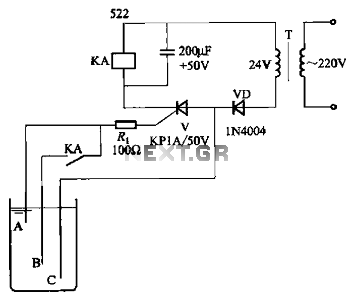
The circuit depicted in Figure 11-14 utilizes a unidirectional thyristor within liquid level automatic control systems. It incorporates electrodes that serve as sensing elements for detecting the level of water or other conductive liquids. The circuit features a current...