
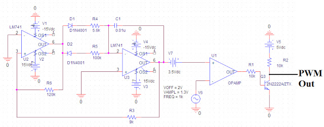
pulse width modulation
PWM can be effectively implemented in power supplies when the source power is switched at a sufficiently high frequency, enabling the output inductor to provide current without allowing it to drop to zero. Since current through an inductor cannot change instantaneously, the inductor current will decrease gradually when the switch is turned off, rather than dropping to zero immediately. As long as the switch is reactivated before the inductor current falls below a useful level, the load experiences a continuous current flow. Similarly, LEDs can be dimmed via PWM by turning them on and off at a frequency higher than the human eye can perceive, while varying the duty cycle to control brightness. A pulse train with a higher duty cycle results in increased brightness, and vice versa. The minimum switching frequency for LEDs is still debated among experts, but it can generally be as low as a few hundred hertz.
PWM techniques are also employed with motors to control rotational speed. As long as the switch is turned on before the motor speed decreases significantly, the motor will perform its intended function. The advantage of PWM over traditional methods, such as using a resistor to reduce voltage, lies in efficiency. Resistive elements in power transfer systems create voltage drops and power loss, which are detrimental. The integration of switching elements into power transfer circuits significantly reduces instantaneous losses. When the switch (transistor) is open, no current flows through the device, resulting in zero power dissipation (P=IV or I²R). When the switch is closed, it acts as a short circuit between the two contacts, leading to zero voltage drop and consequently zero power dissipation in the switch. This means that in both high and low states, the switching element dissipates no power, allowing the load to receive nearly all power drawn from the source. However, PWM is not without drawbacks. The primary limitation is that no switch can operate instantaneously. Each time a transistor is switched, there is a transition time between states, causing the PWM waveform to appear more trapezoidal than square at higher resolutions.
PWM is an essential technique in modern electronic design, providing a method for efficient power management across a wide range of applications. In switched-mode power supplies, PWM facilitates the regulation of output voltage and current, ensuring stable operation while minimizing energy losses. In LED applications, the ability to control brightness without significant heat generation enhances the longevity and performance of lighting systems. For motor control, PWM enables precise speed regulation, improving efficiency and responsiveness in various automation and robotics applications. Understanding the intricacies of PWM, including duty cycle calculations and switching frequency considerations, is vital for engineers aiming to implement effective and reliable electronic circuits.PWM is a highly efficient control scheme used to manipulate the flow of power through various electronic devices. I have seen it most commonly used in switched-mode power supplies, LED dimming circuits, and variable speed motor controls, but there are several more applications.
The concept of PWM draws from the most basic elements of a binary system: on (1) or off (0). At any given moment, switches are turned on or off depending on the feedback signal from the load receiving power. This process allows power to be taken from the source in doses and supplied to the output such that the output remains relatively constant.
Exactly how much power is supplied to the load depends on the duty cycle of the switching system. The duty cycle of a PWM waveform refers to the amount of time relative to an entire switching period that the pulse stays high. It is usually expressed as a percentage or decimal and can vary anywhere between 0% (completely off) to 100% (completely on).
Figures 1-3 show some examples of various duty cycles used for voltage regulation and the math explaining how the load sees an average voltage depending on the switching conditions. The figures assume the switches are operating at 50 kHz (being turned on and off 50, 000 times/second).
In practice, PWM can be implemented in power supplies if the source power is switched at a sufficiently high frequency such that the output inductor can supply current without letting it fall to zero. Current passing through an inductor cannot change instantaneously which means even if the switch from the source is turned off the inductor current will drop steadily instead of falling to zero immediately.
As long as the switch comes back on before the inductor current falls too low to be useful, the load sees a continuous flow of current. Similarly, LEDs can be dimmed using PWM. By turning the LEDs on and off at a higher frequency than the human eye can detect, and varying the duty cycle, you can control the brightness level.
A pulse train with a higher duty cycle will increase the brightness and vice versa. There is still some debate among the experts in the field of LEDs on what the minimum switching frequency should be but in general it can be as low as a few hundred hertz. Lastly, PWM schemes are utilized with motors to regulate the speed of rotation. As long as the switch is turned on before the motor has a chance to decrease appreciably in speed, the motor will continue to perform its intended function.
So why is this scheme better than, say, adding a resistor to drop the voltage before it gets to the external load The answer is efficiency. In any power transfer system, resistive elements are the enemy because they constantly create voltage drops and power loss.
The beauty of including switching elements into a power transfer circuit is that the instantaneous losses are significantly reduced. When the switch (transistor) is open, no current is passing through the device so the power dissipation is zero (P=IV or I2R).
When the switch is closed, the switch acts like a short between the two contacts so the voltage drop is zero and therefore the power dissipation in the switch is again zero. What this all really amounts to is that in both the high and low states the switching element itself dissipates no power meaning the load receives nearly everything drawn from the source.
Unfortunately, we don`t live in a perfect world and even cool schemes like PWM have drawbacks. First and foremost, nothing can switch instantaneously. Every time a transistor is switched there is a transition time in between the states which causes the PWM waveform to look more trapezoidal than square under high enough resolution. During these transit 🔗 External reference
Related Circuits
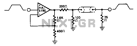
The HA-5190 can drive the 75-ohm coaxial cable with signals up to 2.5 V peak-to-peak without the need for current boosting. In this circuit, the overall gain is approximately unity due to the impedance matching network. The HA-5190 is a...
Power input is to a 7805 5 volt regulator. A pair of LEDs is connected between the 5 volt supply and ground, with current limiting resistors in series and one pin on the AT90S2313 shunts the current through one...
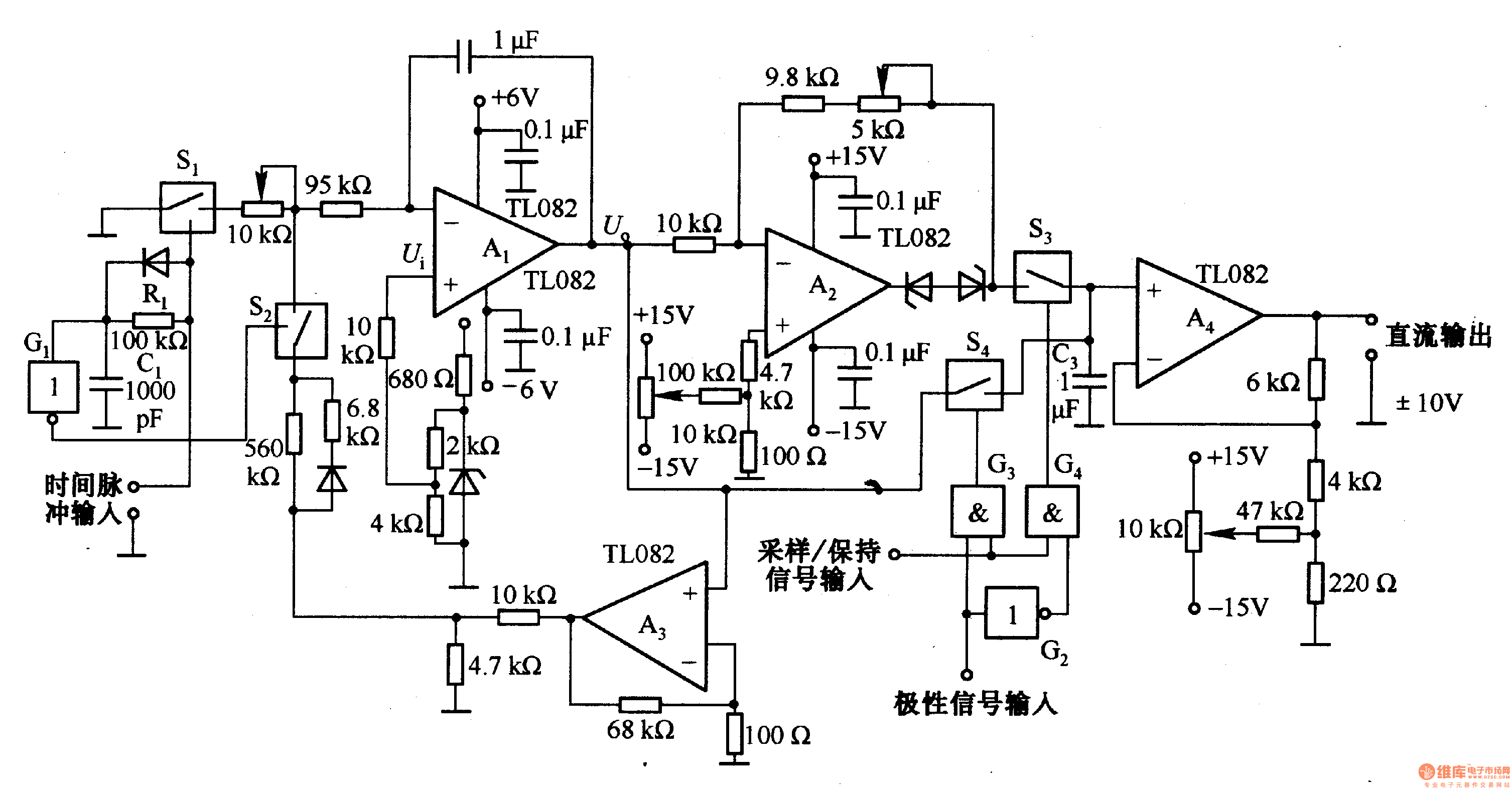
This circuit is designed for pulse width (time) to voltage conversion. According to the component parameters in the diagram, it can convert a pulse width of 0.1 seconds into an output voltage of 10V. When a conversion pulse is...
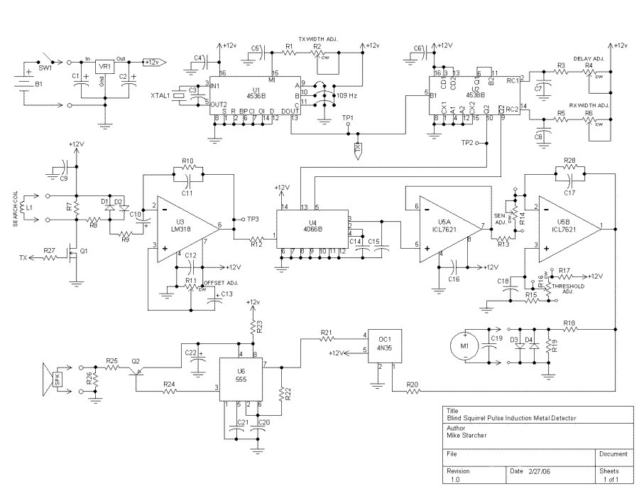
As you can see, there is only one regulated 12 volt supply operating the entire circuit. This allowed me to adjust the offset within an operating window. By using a tantalum capacitor of reasonably high capacity, the signal passes...
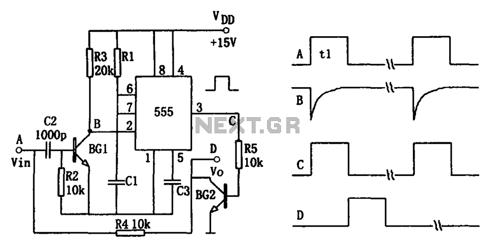
The pulse-width detection circuit is illustrated in the figure and consists of a differential circuit (R2, C2), an amplifier (BG1), a single stabilizing circuit (555, R1, C1), and various other components. The pulse signal Vin (depicted as waveform A)...
A circuit designed to extract and measure the modulated carrier of an infrared remote control. The circuit does not physically separate control pulses from modulation; instead, it amplifies the entire received signal, allowing the waveform to be ideally displayed...