
Frequency Modulated Sound Card Capture
The FM circuit design for audio signals aims to address the limitations of standard sound cards that filter out low-frequency signals. By employing the XR-2206 integrated circuit, the design can effectively generate a carrier frequency and modulate it to capture a broader spectrum of audio signals. The circuit configuration requires careful selection of resistors and capacitors to achieve the desired carrier frequency and modulation range.
The schematic should include the XR-2206, with its pins connected to the appropriate resistors (R2, R3, R5, R6) and capacitors (C2, C4) to define the operating parameters. The input signal should be connected to the designated input pin of the XR-2206, while the output can be taken from the modulation output pin. Proper grounding and power supply connections are essential to ensure stable operation.
To facilitate the dual-channel functionality, two identical FM circuits can be constructed, sharing a common input signal. Each circuit should have its own set of components to maintain independent modulation characteristics. The stereo jack must be correctly wired to accommodate both channels, ensuring that the output can be interfaced with recording equipment or analysis tools.
In summary, the proposed FM circuit serves as a viable solution for capturing low-frequency audio signals that standard sound cards typically filter out. By leveraging the capabilities of the XR-2206 and carefully selecting components, users can achieve a functional and cost-effective solution for audio signal processing.The problem with sound cards is that they bandpass their input signals. So, if you are wanting to record any signals below 20Hz or so, you are out of luck, ordinarily. There are two solutions to this problem that I have found. The first, is that if you are lucky, you can modify your sound card to remove the high-pass filter, which is removing the signals below 20Hz. The first option has a very nice tutorial written by Scott Molloy ( ). Unfortunately, the sound cards that I had access to could not be modified to remove the high-pass filtering (they are actually done in an IC now). The second option is to make a Frequency Modulated circuit, this idea was first published by David Prutchi and Michael Norris in August 19, 2002`s edition of Electronic Design ( ).
This tutorial is based upon their design. The difference is that I have simpified the design and made it dual channel. The total cost should be $15 to $20. The circuit expects a +/-10 volt input signal. The circuit should generate a carrier frequency of approximately 4. 4Khz and a change of frequency of up to 3Khz. A greater range could be used to reduce the signal to noise and increase the upper frequency of the input signal (approximately 200Hz with this circuit). The carrier frequency is mainly determined by resisters R2 and R5 and capacitors C2 and C4. The range of frequency modulation is mainly determined by resisters R3 and R6. With a 10 volt input range having R2 = R3 and R5 = R6 seems to work well. Due to variability in the XR-2206 and the capacitors used for C2 and C4, the actual carrior frequency will probably be off.
If the actual carrior frequency is substantially different between the two, you can try different resistors. In my circuit I ended up using 50K resistors for the lower circuit (R5, R6) because the carrior frequency was higher than I would like using 40Ks.
If you use a lower voltage input range you will need to use smaller resistors for R3 and R5, unfortunately changing these will also change the carrior frequency some, so you will need to play around with different resistor combinations until you find something that works well for you. The optimal range for the carrior frequency should be between 4 and 5Khz. To measure the output frequencies of the device I captured a second of sound and then used a spectrum analizer to measure the frequency which had the strongest power; I used Matlab to do this, but there are probably other tools as well.
Make sure to measure the carrier frequency when 0 volts is being fed into the circuit, other wise it will default to an input of 3 volts (due to the design of the XR-2206). Another "trick" that can be used to measure the carrier frequency is that when the CarrierFreq value in the code below is right, it should return approximately 0 when 0 volts is being inputed.
So, changing CarrierFreq higher or lower should allow you to find the value that gets you the closest to 0. 1 stereo jack - Radio Shack`s 1/8" Stereo Panel-Mount Phone Jack (274-246) would do, it costs $2. 99; just make sure that it has a ring bolt because this is how we attach the face plat to the card. The only complication is that the card wasn`t stable enough to insert the stereo cable without any additional support, so I added a loop of tape at the top of the card to hold it in place (you can see the blue tape on the upper right hand side).
float tmpPhase1 = atan2f(out2[i][0] * e[port][i][1] + out2[i][1] * e[port][i][0], out2[i][0] * e[port][i][0] - out2[i][1] * e[port][i][1]); // copy the down sampled data into our storage buffer, we have to scale it because the output atan2`s is in radians (i. e. -Pi to Pi) Using more professional sound cards, ones that can record at 96Khz or even 192Khz would allow for greater bandwidth.
It would allow for either a higher frequency range for the input signal or allow for multiple channels to be recorded on the same input. Currently you in theory can h 🔗 External reference
Related Circuits
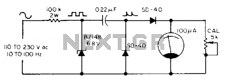
The meter utilizes a zener diode to convert input sine waves into square waves. After calibration with a 5 k ohm potentiometer, the 100 µ meter provides a direct reading in hertz. The circuit employs a zener diode as a...
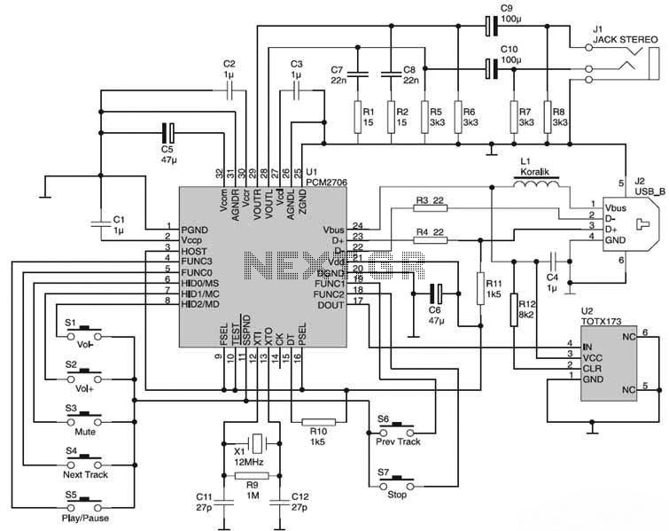
The USB Sound Card circuit is based on the PCM2706, which is designed for USB audio applications. The PCM2706 includes a USB controller module, eliminating the need for additional programming of the integrated circuit (IC). The computer system will...
This simple tuned radio frequency receiver was designed and constructed in the mid-1990s. The receiver was tested under urban and field conditions, in varying temperatures. This straightforward circuit exhibits high sensitivity, good sound quality, and reliability. A signal received...
This circuit utilizes the versatile MAX038 function generator. While some advanced features of this IC are disabled in this configuration, it is capable of generating sine, triangle, and square waves by adjusting the A0 and A1 pins (refer to...
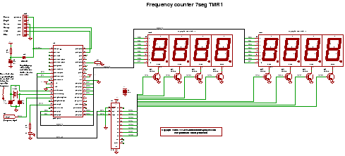
C code for a frequency counter circuit operating up to approximately 50 MHz, utilizing a multiplexed seven-segment display and employing Timer 1 to count the edges of the input signal. The frequency counter circuit described operates effectively within the range...
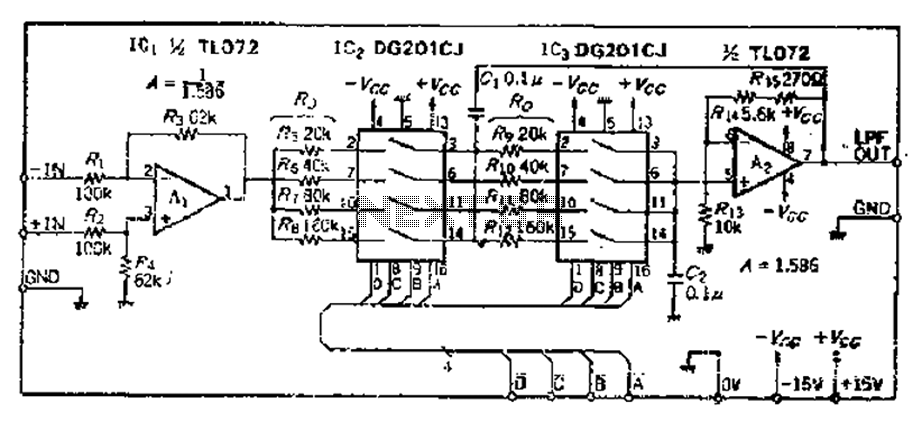
The circuit primarily consists of two Butterworth filters, designed to create a feedback amplifier with a gain of approximately 0.707. It features a differential input amplifier, where one input is grounded, resulting in a single input terminal. The attenuation...
Warning: include(partials/cookie-banner.php): Failed to open stream: Permission denied in /var/www/html/nextgr/view-circuit.php on line 713
Warning: include(): Failed opening 'partials/cookie-banner.php' for inclusion (include_path='.:/usr/share/php') in /var/www/html/nextgr/view-circuit.php on line 713