
mic circuit
The described circuit provides a robust solution for analog voltage measurement and transmission, suitable for various applications where low power consumption and high input impedance are critical. The MIC 640's dual operational modes enhance its versatility, allowing it to adapt to different operational requirements, whether in automated or controlled environments. The careful selection of components ensures optimal performance while maintaining low power draw, making the circuit efficient for battery-operated or energy-sensitive applications. The design emphasizes reliability and accuracy, essential for precision measurement tasks in electronic systems.This tour, available in Stainless DIL 8 legs, can measure 4 analog voltage independent between 0 and 5 volts, and send the result of this measure in the form of four characters on a standard asynchronous serial link. Its serial output is directly TTL or CMOS compatible and can be connected to a serial input RS 232 by simply adding a resistor.
The MIC 640 can operate in automatic mode, thus sending the result of four steps every second, or in command mode, in which case it sends the result of four measures under the control of external logic signal. In this latter method that we use here. Its consumption is extremely low, it is possible to feed signals from the unused serial port RS 232, subject of course not to waste the little energy available in external circuits involved too greedy.
This circuit, easily available in France, costs less than 18 euro which makes it an ideal candidate for this achievement we will find the schema without tarder. Si you want more information about the MIC 640;`s complete data sheet entirely in French, is available for download by clicking this link.
The heart of the module is obviously the MIC 640, spotted IC1 on the figure below. It is directly connected to the serial input RS 232 PC via limiting resistor R1 current. His entry called CTRL to define its mode of operation. Left to the body, it makes it automatically perform a conversion on each input per second, whereas if it is reduced to levels as high as in this case, it triggers a conversion of each entry at each grounding. These earthed take place through the transistor Q1 controlled by the serial data output TXD of RS 232, via the diode D4.
This same output is through the diode D3 and this time the capacitor C3, to produce the negative supply voltage of the input stage that we discover in a moment. The control lines DTR and RTS serial interface they provide for the positive supply via diodes D1 and D2.
This voltage is unregulated, is the positive power of the input stage. By cons, it is regulated to 5 volts through IC2 so that it feeds a voltage very stable MIC 640. As the current and available for both the positive supply for the negative supply is still low (10 mA max), I had to carefully choose the components used and they will not be replaced under any pretext. IC2 is indeed a regulator 5 volts 3 feet very low: in one case in 2936 SM Z5 which absorbs only 500 uA.
For information, its "equivalent" the 78L05 consumes 3 mA in the same situation! The input stage meanwhile was achieved using four operational amplifiers effect transistor field-mounted voltage followers. This confers to the module input impedance greater than 100 MW. All four amplifiers are combined in one box, referenced LF 444 at National Semiconductor, whose total consumption does not exceed 800 uA for the four amplifiers!
Again, no question of putting such a TL 084 which face voracious with its 5. 6 mA! This input stage is protected from excessive voltages through resistors R7 to R10 and diodes D6 to D13. If you precede the various stages of converting physical quantities / voltage, you can possibly do without protection diodes that degrade somewhat the very high input impedance of 444 MQ due to their leakage current.
It is in fact only 50 pA maximum input of 444 LF while a diode, even small leaks, easily misses 1 nA or 20 times more! 🔗 External reference
Related Circuits
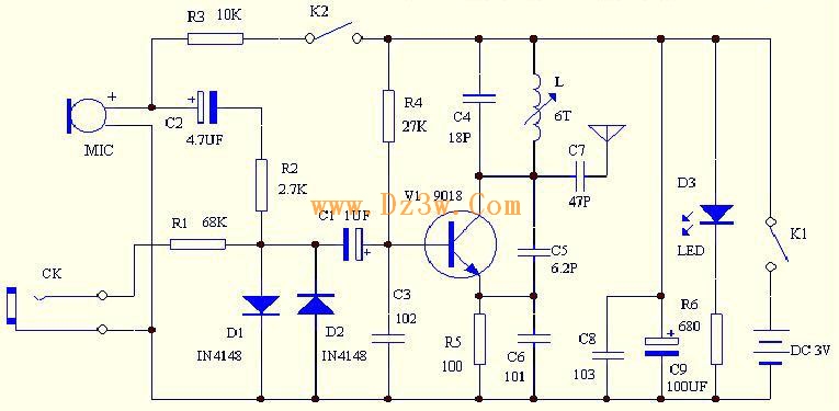
C4 and L form a resonator, where the resonant frequency corresponds to the FM transmitting power of the microphone. According to the component parameters in the diagram, the transmission frequency can range from 88 to 108 MHz. The frequency...
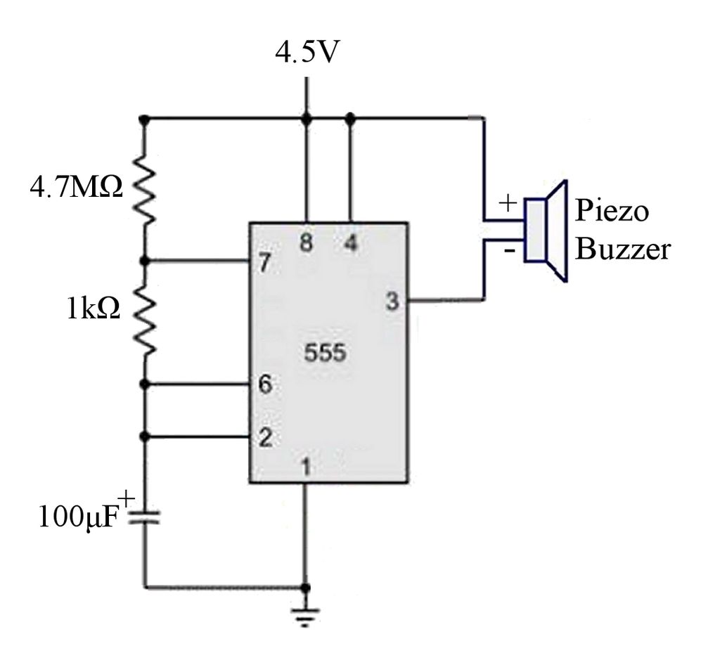
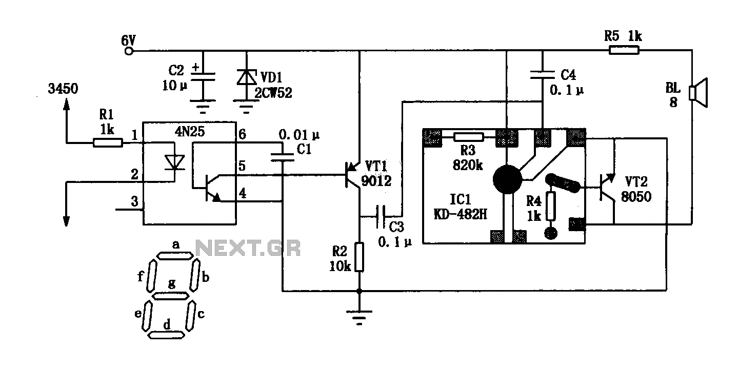
The circuit is a basic 555 timer circuit in astable mode. In this configuration, the integrated circuit (IC) generates a brief pulse to the buzzer at regular intervals. The 555 timer in astable mode operates as an oscillator, producing a...

This 555 timer circuit temperature monitoring system project can monitor temperature at up to four points. The system allows for the selection of whether the alarm should be triggered when the temperature increases or decreases, depending on the resistance...
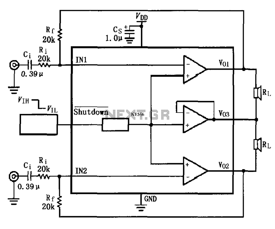
The LM4910 typical circuit is designed for a two-channel amplifier. The left and right channel audio signals are input to the LM4910 (in an MSOP/SO package) at pins 1 and 2. The output signals are delivered from pins 6,...
The General Dynamic LED digital clock lacks a timekeeping function, but by adding a simple circuit, it can incorporate this feature. The integrated circuit (IC) includes a programmable mute function, which is inactive from 23:00 to 5:00 to avoid...
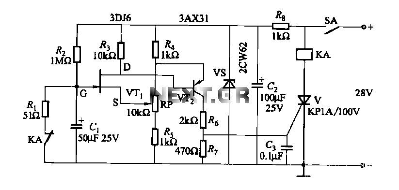
FET relay circuit 2 is essentially a JS-20 time relay circuit. When the switch SA is open, the relay device KA remains in the released state. Once switch SA is closed, the delay period begins. After a specified duration,...
Warning: include(partials/cookie-banner.php): Failed to open stream: Permission denied in /var/www/html/nextgr/view-circuit.php on line 713
Warning: include(): Failed opening 'partials/cookie-banner.php' for inclusion (include_path='.:/usr/share/php') in /var/www/html/nextgr/view-circuit.php on line 713