
Microchip PIC Programmer

This programming circuit is designed to facilitate the development and debugging of Microchip's various processor families. The circuit employs an In-Circuit Serial Programming (ICSP) interface, which allows programming and debugging while the microcontroller remains soldered onto the PCB. This feature significantly enhances convenience and efficiency, especially in iterative development processes.
The circuit typically includes a microcontroller programmer, a connection interface, and a power supply circuit. The programmer interfaces with the target microcontroller through the ICSP header, which consists of at least five pins: MCLR (Master Clear), Vpp (Programming Voltage), Vdd (Supply Voltage), Vss (Ground), and Data (Serial Data Line). Depending on the specific microcontroller model, additional pins may be utilized for programming and debugging purposes.
The programmer's design must ensure that it can supply the necessary programming voltage levels and current requirements as specified in the datasheets of the target microcontrollers. It is essential to include appropriate resistors and capacitors in the circuit to stabilize the signals and protect against voltage spikes that may occur during programming.
In addition to the physical connections, software support is crucial for the operation of the programmer. The programming software must be compatible with the intended processor families and should provide a user-friendly interface for uploading firmware, verifying memory, and debugging code.
Overall, the circuit serves as a versatile tool for developers working with Microchip processors, streamlining the programming process and enhancing productivity in embedded system design.This circuit can program any MicroChip processor from 6 pins to 40 pins processors. The programmer supports: PIC12, PIC16, PIC18, dsPIC24, dsPIC30 families, and uses an ICSP header thus not requireing to remove the PIC from the circuit each time it needs to be programmed. 🔗 External reference
Related Circuits
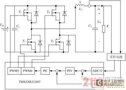
Traditional UPS systems use analog circuit control, which presents significant limitations for both manufacturers and users, regardless of whether they employ technology or SPWM technology. With advancements in information technology, the introduction of high-speed digital signal processing chips, known...
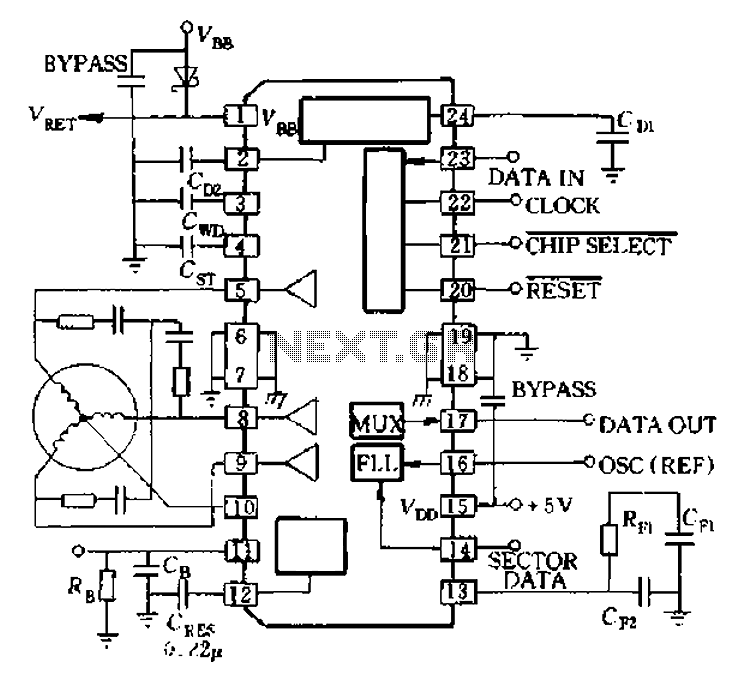
A8902 is a typical application wiring diagram. After a system failure signal from the delay island and CB 11 feeds into the motor brake, the system stops functioning until the RESET signal arrives, at which point the motor restarts. The...

The FT232RL USB to Serial UART (TTL) Adapter is an affordable and straightforward solution for connecting PIC, AVR, or ATMEGA microcontrollers to a PC or Mac via a USB interface. The FT232RL chip is noteworthy for its compliance with...
This ISP programmer can be utilized for both in-system programming and as a standalone SPI programmer for Atmel ISP programmable devices. The programming interface is compatible with the STK200 ISP programmer hardware, allowing users of the STK200 to also...

AVR has two different programming modes called Parallel Programming Mode (Parallel Mode) and Serial Downloading Mode (ISP mode). In Parallel Mode, the programming is done using multiple data lines simultaneously, allowing for faster programming speeds. This mode is typically...
This project outlines the construction of a digital voltmeter utilizing a PIC microcontroller. A character LCD based on the HD44780 is employed to display the measured voltage. The PIC microcontroller used is the PIC16F688, which features 12 I/O pins,...