
PIC16F688 Digital Voltmeter
The digital voltmeter circuit leverages the capabilities of the PIC16F688 microcontroller, which integrates an analog-to-digital converter (ADC) that allows for precise voltage measurements. The use of the HD44780 character LCD provides a user-friendly interface for displaying the measured voltage readings. The design incorporates a resistor divider network formed by resistors R1 and R2, which is crucial for scaling the input voltage to a level that the microcontroller can safely handle. The selection of resistor values is pivotal in determining the input voltage range and ensuring that the ADC operates within its specified limits.
In this configuration, the input voltage is fed into the resistor divider, where R1 and R2 work together to reduce the voltage from the maximum of 20V down to a maximum of 5V, making it suitable for the ADC input of the PIC16F688. The calculated output voltage from the divider can be expressed using the voltage divider formula: Vout = Vin * (R2 / (R1 + R2)). Therefore, careful selection of R1 and R2 is necessary to maintain the desired voltage range.
The inclusion of a 5.1V zener diode serves as a protective measure, ensuring that any voltage spikes do not exceed the maximum rating of the PIC's analog input. This component helps safeguard the microcontroller from potential damage due to over-voltage conditions, which could occur if the input voltage inadvertently exceeds the expected range.
The LCD is interfaced in 4-bit mode, which reduces the number of data lines required for communication, simplifying the circuit design and minimizing the use of I/O pins on the microcontroller. The ICSP header is a valuable feature during the development phase, allowing for easy firmware updates and debugging without the need to remove the microcontroller from the circuit.
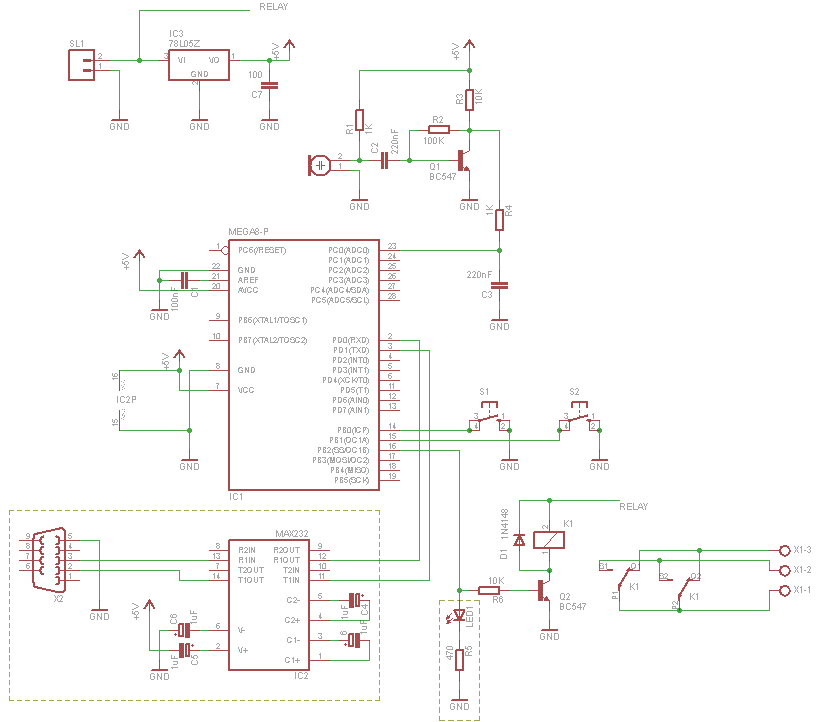
For optimal performance, a regulated power supply of +5V is essential. The LM7805 linear voltage regulator is a reliable choice for providing this stable voltage, ensuring that the ADC operates accurately. The precision of the resistors used in the voltage divider and the stability of the reference voltage directly influence the overall accuracy of the voltmeter. Consequently, using high-precision resistors and ensuring a stable Vdd are critical for achieving accurate voltage measurements.This project describes how to make a digital voltmeter using a PIC microcontroller. A HD44780 based character LCD is used to display the measured voltage. The PIC microcontroller used in this project is PIC16F688 that has 12 I/O pins out of which 8 can serve as analog input channels for the in-built 10-bit ADC. The voltage to be measured is fed to one of the 8 analog channels. The reference voltage for AD conversion is chosen to be the supply voltage Vdd (+5 V). A resistor divider network is used at the input end to map the range of input voltage to the ADC input voltage range (0-5 V). The technique is demonstrated for input voltage ranging from 0-20 V, but it can be extended further with proper selection of resistors and doing the math described below.
Since the PIC port cannot take 20V input directly, the input voltage is scaled down using a simple resistor divider network. The resistors R1 and R2 scale down the input voltage ranging from 0-20V to 0-5V, before it is applied to PIC16F688`s analog input channel, AN2.
A 5. 1V zener diode connected in parallel between the port pin AN2 and the ground provides protection to the PIC pin in case the input voltage accidentally goes beyond 20V. The LCD display is connected in 4-bit mode, and the ICSP header makes the firmware development easier as you can reprogram and test the PIC while it is in circuit.
When you are satisfied and want to transfer the circuit from the breadboard to a PCB or general-purpose prototyping board, you don`t need the ICSP header. The circuit diagram and the prototype built on a breadboard are shown below. Important: You need a regulated +5V supply for accuracy of the output. The ADC uses Vdd as the reference for conversion, and all computations are done with Vdd = 5V. You can get a regulated +5V using a LM7805 linear regulator IC. The accuracy depends upon the accuracy of the resistors at the input end and the stability of reference voltage, Vdd = +5V.
I found Vdd is stable to +5. 02 V. I measured R1 and R2, and their values are 1267 and 3890 Ohms. So this gives, 🔗 External reference
Related Circuits

A10-V zener diode is utilized to extend the measurement range of a voltmeter from 0-5 V to a range of 10-15 V. An LED bar graph illuminates one segment for every 0.5 V increase above 10 V. Additionally, the...
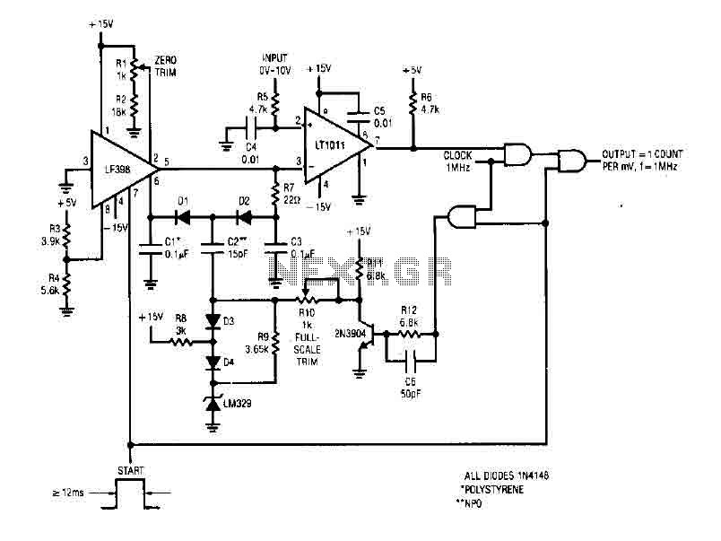
The simple 4-digit converter circuit has an output count of 1, designed for a frequency range from f-IMHz to 10.000 MHz. All diodes used in the circuit are IN4146 "POLYSTYRENE" NPO. The circuit utilizes the LF398 at the input...
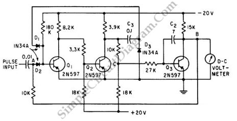
This is a Peak Voltmeter circuit. This circuit can be viewed as a pulse stretcher, which captures fast pulse signals to be measured by a slow response voltmeter. The Peak Voltmeter circuit is designed to accurately measure the peak voltage...
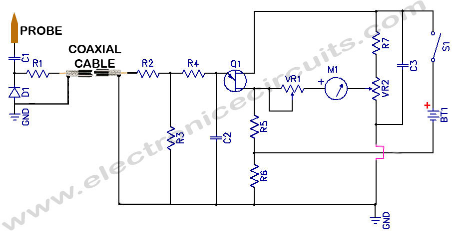
Sensitive RF Voltmeter Probe Circuit. This circuit measures RF voltages beyond 200 MHz and up to approximately 5V. The sensitive RF voltmeter probe circuit is designed to accurately measure radio frequency (RF) voltages in the range exceeding 200 MHz,...
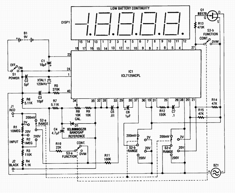
This 4 1/2-digit DVM circuit is built around a Maxim ICL7129ACPL A/D converter and LCD driver. An ICL8069 CCZR 1.2-V band-gap reference diode is used for a voltage reference. S2a-b-c select one of four ranges up to 200 V...
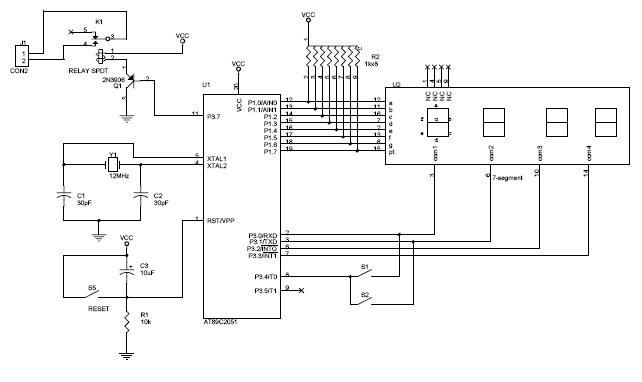
The circuit diagram above illustrates the Clock Controller V1.1. Pins P3.0 to P3.3 are connected to the base of a 4-PNP transistor, specifically the 2N2907, which is used to sink current. The Clock Controller V1.1 circuit is designed to manage...
Warning: include(partials/cookie-banner.php): Failed to open stream: Permission denied in /var/www/html/nextgr/view-circuit.php on line 713
Warning: include(): Failed opening 'partials/cookie-banner.php' for inclusion (include_path='.:/usr/share/php') in /var/www/html/nextgr/view-circuit.php on line 713