
Phase Locked Loop (PLL) Operating Principle Phase Detector VCO LPF
 Operating Principle Phase Detector VCO LPF")
A Phase Locked Loop (PLL) is an essential electronic circuit used in various applications such as frequency synthesis, demodulation, and clock recovery. The core functionality of a PLL is to synchronize an output signal's phase and frequency with a reference signal. The primary components of a PLL include a Phase Detector (PD), a Voltage Controlled Oscillator (VCO), and a Low Pass Filter (LPF).
The Phase Detector compares the phase of the input reference signal with the phase of the output signal from the VCO. The output of the Phase Detector is a voltage signal that represents the phase difference between these two signals. This voltage signal is then passed through the Low Pass Filter, which smooths out the high-frequency components and provides a steady control voltage.
The control voltage generated by the LPF is fed into the Voltage Controlled Oscillator. The VCO generates an output frequency that is proportional to the input control voltage. When the PLL is locked, the output frequency of the VCO matches the frequency of the reference signal, and the phase difference is minimized.
In summary, the PLL operates by continuously adjusting the VCO based on the phase difference detected by the PD, ensuring that the output signal remains in phase and frequency with the reference signal. This feedback mechanism allows for stable and accurate signal processing, making PLLs critical in communication systems, signal processing, and clock generation applications.Phase Locked Loop (PLL) Operating Principle with block diagram showing Phase Detector, Voltage Controlled Oscillator, Low Pass Filter.. 🔗 External reference
Related Circuits
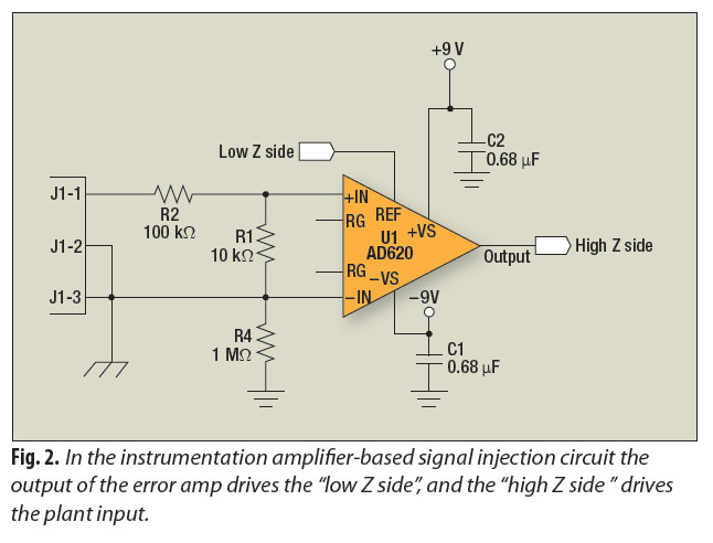
A signal-injection circuit for control-loop analysis is flat from DC to 200 kHz, isolated from chassis ground, and easily constructed with a readily available instrumentation amplifier. The signal-injection circuit is designed to facilitate control-loop analysis by providing a stable and...
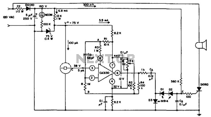
An ionization chamber in conjunction with a high-impedance CA3130 operational amplifier is utilized to detect the presence of smoke. When smoke is detected, the CA3130 ceases oscillation, which in turn triggers the S106D silicon-controlled rectifier (SCR) to sound an...
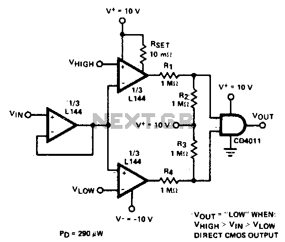
The detector employs three sections of an L144 and a CMOS NAND gate to create a low-power voltage monitor. The 1 MΩ resistors R1, R2, R3, and R4 convert the bipolar ±10 V swing of the operational amplifiers to...
The LM134 is an effective temperature sensor due to its highly linear output characteristic. As a current output device, it remains unaffected by certain environmental factors. The LM134 is a three-terminal device that operates as a current source, providing a...
This circuit is designed to indicate, via a flashing LED, when room noise exceeds a predetermined threshold, which can be set to one of three fixed levels: 50, 70, or 85 dB. Two operational amplifiers (op-amps) are utilized to...
One of the simplest methods of metal detection is through a beat frequency oscillator. The circuit consists of two balanced oscillators: one provides a reference signal, while the other acts as the detector element. The frequency of the reference...