
MIDI Tester Schematic diagram

The circuit utilizes the 6N139 opto-isolator to separate the MIDI signal from the receiving device, ensuring that any electrical noise or ground loops do not affect the performance of the MIDI system. The opto-isolator consists of an LED and a phototransistor, which are optically coupled but electrically isolated from each other.
In this configuration, the MIDI signal is applied to the LED side of the 6N139. When the current loop is activated by the MIDI signal, the LED emits light, which is detected by the phototransistor on the output side. This results in a corresponding TTL pulse, which can be used by digital devices for further processing.
The circuit design should include appropriate resistors to limit the current through the LED to a safe level, typically around 10-20 mA, ensuring reliable operation of the opto-isolator. The output from the phototransistor can be connected to the input of a microcontroller or any other digital logic device that requires TTL level signals.
By implementing this approach, the integrity of the MIDI data transmission is maintained while providing electrical isolation, which is critical for preventing interference and protecting sensitive components in the MIDI system.As MIDI data is transmitted between instruments using a current loop, a opto-isolator (6N139) is used to convert this current loop into TTL pulses. Th.. 🔗 External reference
Related Circuits
The fundamentals of crystals have not changed since this article appeared in a 1960 edition of Popular Electronics. The methods for growing, cutting, and packaging crystals have evolved significantly. Understanding their operation at the atomic level has also advanced...
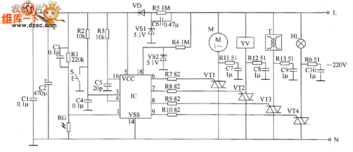
The industrial fuel oil furnace controller circuit consists of a power supply circuit, a testing and ignition control circuit, and a control implementation circuit, as illustrated in the accompanying diagram. The power supply circuit includes a step-down capacitor (C6),...
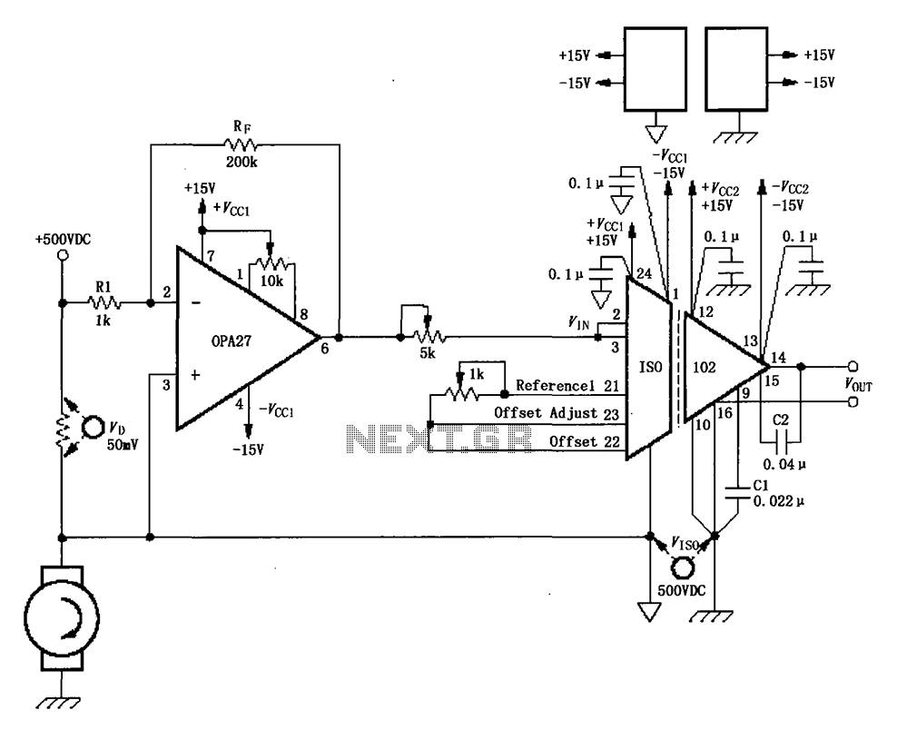
The circuit depicted in the figure consists of an ISO102 and OPA27 for measuring DC current at a voltage of +500V. It is configured between a +500V DC voltage source and a sampling resistor that is in series with...

This circuit illustrates the modifications made due to a blown resistor on the backside, which was soldered in place. The issue was traced back to this specific resistor. Currently, the pattern change switch is set to Option 3, which...
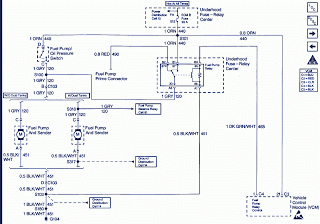
Pump prime connector, power distribution cell, fuel pump and sender, dual tanks, fuel pump balance relay, vehicle control module, underhood fuse relay, ECM fuse. The described components are integral to the operation and management of a fuel system in a...
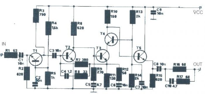
The T1 transistor must be of the BF200 type (or a similar variant), while the other transistors can be of the BF214 type. To achieve high efficiency, the antenna amplifier should be positioned at a short distance from the...