
Emergency LED Light LED-716 Emergency Light Schematic

The circuit features a power supply that feeds into a control unit, which manages the operation of a light bulb based on the selected options. The blown resistor, which has been replaced, plays a critical role in regulating current flow through the circuit. When the pattern change switch is set to Option 3, the circuit allows maximum current to flow, activating the light bulb at full brightness. This setting is ideal for applications requiring extended illumination, as indicated by the backup time of 8 to 10 hours.
The circuit may include a microcontroller or a simple switching mechanism that detects the position of the pattern change switch. The transition to Option 2, which is intended for turning off the bulb, likely interrupts the current flow, ensuring that the light is deactivated when not needed. This feature not only conserves energy but also prolongs the lifespan of the light bulb.
In summary, the circuit design incorporates a robust resistor to prevent overheating and potential failure, while the pattern change switch provides user control over the light output. The estimated backup time indicates an efficient energy storage solution, ensuring reliable performance during extended use.Here you can see that what i did in this circuit. because the resistor on the back side ( which i have soldered) was blown out. so the root of problem was that specific resistor. And in this case, the pattern change switch is on Option 3 i. e on Full light. the back up time will be 8-10 hours. also note that, option 2 is for turning off the Bulb l ight. 🔗 External reference
Related Circuits
Introduction and disclaimer for individuals interested in a fading dome light (also referred to as courtesy light or theatre lighting) without incurring high costs. A fading dome light circuit is designed to create a gradual illumination effect, enhancing the aesthetic...
The following circuit illustrates the sensor circuit diagram for automatic room lights. This circuit is based on the CD4017 integrated circuit (IC) and features the use of two light-dependent resistors (LDRs). The automatic room light circuit utilizes the CD4017 decade...
The Boss SD-1 Super OverDrive is a pedal characterized by a straightforward design, incorporating a dual operational amplifier (uPC4558C) and six transistors, along with an asymmetric overdrive circuitry that emulates the classic, natural growl of a tube amplifier. It...
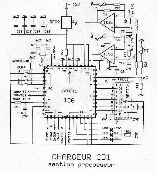
Note first the battery to be treated at the center of the figure. It is connected to contacts of a relay. The diagram shows the relay at rest. Under these conditions the battery is in SHOCK. His pole -...
The circuit is designed to operate with an audio power amplifier that uses 18V-0V-18V power rails. The specific voltage is not critical, but the feedback is referenced to an LED chain connected to a 12V rail, necessitating a separate...
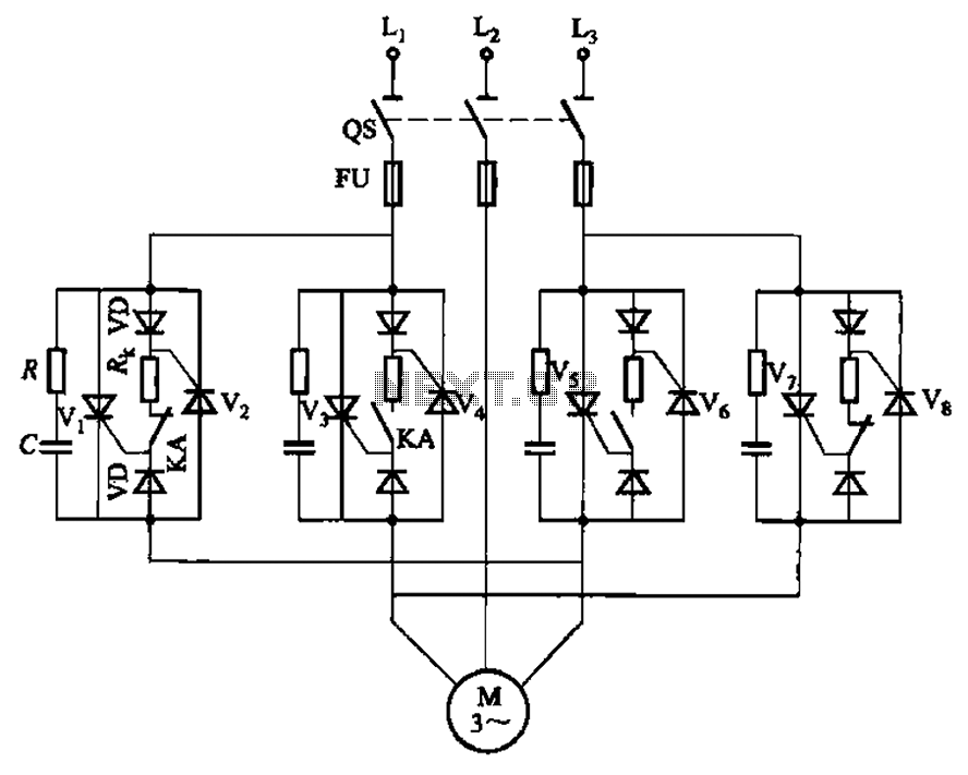
The circuit depicted in Figure 3-69 is designed for applications requiring frequent timing control for motor reversing operations. In this configuration, thyristors V1, V2, V7, and V5 are utilized for positive control of rotation, while thyristors V3, V4, and...