
Mini-Drill Control
This circuit serves as an effective solution for maintaining consistent RPM in small DC motors despite variations in load conditions. The use of a voltage regulator allows for dynamic adjustment of the output voltage, ensuring that the motor operates efficiently under varying operational demands. The design incorporates feedback mechanisms through the use of transistors and resistors, which facilitate real-time monitoring and adjustment of the current flowing through the motor.
Key components such as IC1, T1, and T2 are crucial for the regulation process. IC1 functions as the primary voltage regulator, while T1 acts as a pass transistor, allowing for higher current handling capabilities. T2 serves as a switch that activates additional current paths when the load increases, ensuring that the motor receives sufficient voltage to maintain its performance.
The resistors R1 and R2 are strategically placed to create a feedback loop, allowing for proportional control of the output voltage based on the motor's current draw. This feedback loop is essential for the stability and responsiveness of the circuit, enabling it to react quickly to changes in load conditions.
Furthermore, the circuit's adaptability to different motor specifications is a significant advantage, allowing for fine-tuning of the RPM settings via potentiometer P1. This feature is particularly beneficial in applications where precision is critical, as it enables users to optimize the motor's performance for specific tasks.
Overall, this speed control circuit exemplifies effective design principles in electronics, providing a reliable and efficient method for managing small DC motor operations across various applications. This circuit is intended as a revolution control for small dc motors as fitted, for instance, in small electric drills ( such as used for precision engineering and for drilling boards, among others). The behavior of these motors, which are normally permanent magnet types, is comparable to that of independently powered motors. In theory, the rpm of these motors depends solely on the applied voltage. The motor adjusts its rpm until the counter emf generated in its coils is equal to the applied voltage.
There is, unfortunately, a drop across the internal resistance of the motor, which causes the rpm to drop in relation to the load. In other words, the larger the load, the larger the drop across the internal resistance and the lower the rpm.
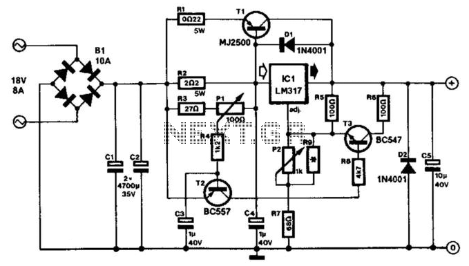
* This circuit provides a kind of compensation for the internal resistance of the motor: when the current drawn by the motor rises, the supply voltage is increased automatically to counter the fall in rpm. The circuit is based on an enhanced voltage regulator that consists of IC1 and Tl, which provides a reasonably large output current (even small drills draw 2-to-5 A).
The "onset" supply voltage, and thus the rpm, is set by P2. Because of emitter resistance Rl, the currents through IC1 and Tl will be related to one another in the ratio that is determined by Rl and R2. Owing to this arrangement, the internal short-circuit protection of IC1 will also, indirectly, provide some protection to Tl.
As soon as the current drawn exceeds a certain value, T2 will be switched on. This results in a base current for T3 so that R5 is in parallel (more or less) with R6. This arrangement automatically raises the output voltage to counter a threatened drop in rpm. The moment at which this action occurs is set by PI, so this circuit can be adapted pretty precisely to the motor used. If only very small motors are likely to be used, the power supply (transformer and bridge rectifier) can be rated more conservatively.
As a guide, the current in the transformer secondary should be about 1.5 times the maximum dc output current. 🔗 External reference
Related Circuits
The circuits on this page are for motor controls using Push buttons and would typically be found in commercial and industrial installations. The circuits do not show the wiring of the motors themselves as this depends on the particular...
A bidirectional three-layer trigger for a triac allows triggering on both half-cycles, with the activation point determined by a 1-megohm potentiometer setting. The triac's rating dictates the load size it can manage. This circuit combines two functions: it serves...
Carefully examine the following circuit diagram and attempt to construct the circuit on a breadboard first. If it functions correctly, proceed to create its PCB version. The circuit diagram serves as a blueprint for constructing an electronic circuit on a...
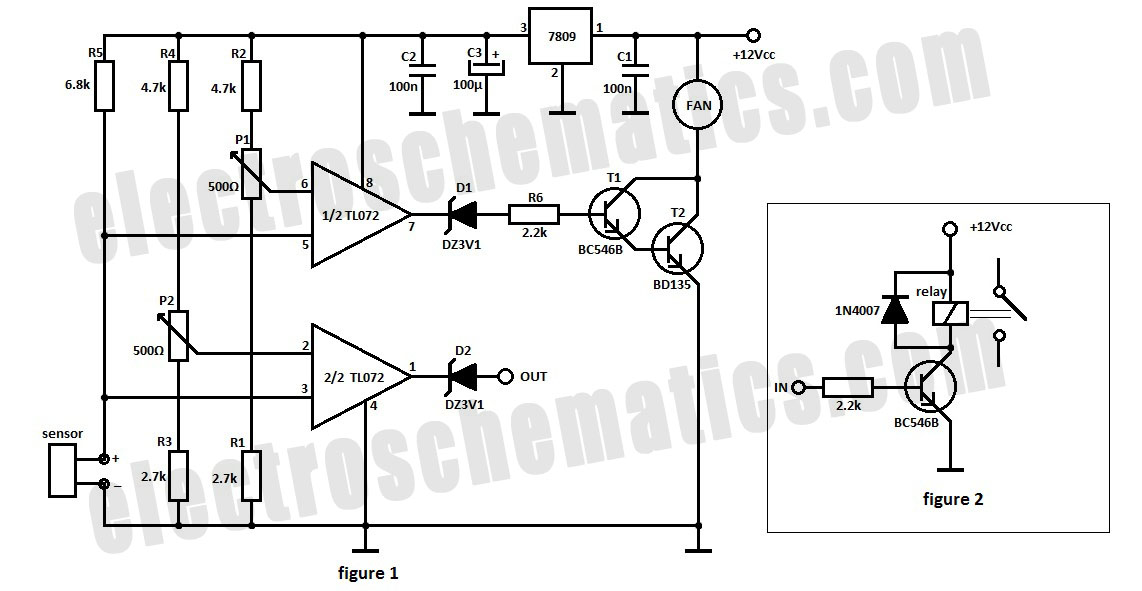
The automatic fan controller circuit depicted in the schematic features two comparators with distinct triggering points that can be adjusted independently. LM135 or... The automatic fan controller circuit is designed to regulate fan operation based on temperature variations. It employs...
The following circuit illustrates a 2500W Phase Control Circuit Schematic. Features include a ground-tied trigger output that is disabled, and a low voltage input. The 2500W Phase Control Circuit is designed to regulate the power delivered to a load by...

Quasi square wave resonant converters, also referred to as quasi resonant (QR) converters, facilitate the design of flyback Switch Mode Power Supplies (SMPS) with diminished Electro Magnetic Interference (EMI) and enhanced efficiency. Due to their low noise generation, QR...