
Mini-MosFet Audio Amplifier
The audio amplifier circuit described is designed to achieve high performance with a minimal component count, leveraging a combination of transistors and passive components to deliver efficient power amplification. The use of low-noise, high-gain NPN transistors such as the BC550C ensures that the amplifier maintains a low distortion profile, critical for audio applications. The design incorporates a shunt feedback configuration, which enhances stability and linearity, allowing for a clean amplification of audio signals.
The power stage utilizes a combination of N-channel and P-channel MOSFETs, such as the IRF530 and IRF9530, which provide robust output capabilities while maintaining thermal efficiency. The choice of components, including resistors with appropriate power ratings and capacitors with suitable voltage ratings, ensures that the circuit can handle the demands of audio amplification without compromising performance.
The regulated DC power supply is a vital aspect of this design, as it not only provides the necessary voltage and current for operation but also contributes to the overall noise performance of the amplifier. By implementing a high-quality voltage regulator capable of delivering over 2 Amps, the circuit can maintain stable operation across varying load conditions, further enhancing audio fidelity.
In terms of user interaction, the inclusion of potentiometers allows for fine-tuning of the amplifier's gain and output characteristics, enabling users to customize the audio output to their preferences. The careful selection of component values and configurations ensures that the amplifier can be effectively calibrated for optimal performance, making it suitable for a variety of audio applications.R1_2K2 1/4W Resistor R2_27K 1/4W Resistor R3, R4_2K2 1/2W Trimmers Cermet or Carbon (or 2K) R5_100R 1/4W Resistor R6_1K 1/4W Resistor R7, R8_330R 1/4W Resistors C1_22 µF 25V Electrolytic Capacitor C2_47pF 63V Polystyrene or Ceramic Capacitor C3, C4_100 µF 50V Electrolytic Capacitors C5_2200 µF 50V Electrolytic Capacitor Q1_BC550C 45V 100mA Low noise High gain NPN Transistor Q2_IRF530 100V 14A N-Channel Hexfet Transistor (or MTP12N10) Q3_IRF9530 100V 12A P-Channel Hexfet Transistor (or MTP12P10) This project was a sort of challenge: designing an audio amplifier capable of delivering a decent output power with a minimum parts count, without sacrificing quality. The Power Amplifier section employs only three transistors and a handful of resistors and capacitors in a shunt feedback configuration but can deliver more than 18W into 8 Ohm with <0.
08% THD @ 1KHz at the onset of clipping (0. 04% @ 1W 1KHz and 0. 02% @ 1W 10KHz) and up to 30W into a 4 Ohm load. To obtain such a performance and to ensure overall stability of this very simple circuitry, a suitable regulated dc power supply is mandatory. This is not a snag because it also helps in keeping noise and hum of the preamp to very low levels and guarantees a predictable output power into different load impedances.
Finally, as the amplifier requires only a single rail supply, a very good dc voltage regulator capable of supplying more than 2 Amps @ 40V can be implemented with a few parts also. Switch off the supply, disconnect the Multimeter and reconnect it, set to measure at least 1Amp fsd, in series to the positive supply (the possible use of a second Multimeter in this place will be very welcomed).
Those lucky enough to reach an oscilloscope and a 1KHz sine wave generator, can drive the amplifier to the maximum output power and adjust R3 in order to obtain a symmetrical clipping of the sine wave displayed. P1_50K Log. Potentiometer (or 47K) (twin concentric-spindle dual gang for stereo) P2, P3_100K Linear Potentiometers (twin concentric-spindle dual gang for stereo) R1_220K 1/4W Resistor R2_100K 1/4W Resistor R3_2K7 1/4W Resistor R4, R5_8K2 1/4W Resistors R6_4K7 1/4W Resistor R7, R8, R13_2K2 1/4W Resistors R9_2M2 1/4W Resistor R10, R11_47K 1/4W Resistor R12_33K 1/4W Resistor R14_470R 1/4W Resistor R15_10K 1/4W Resistor R16_3K3 1/4W Resistor (See Notes) C1, C2, C9_470nF 63V Polyester Capacitors C3, C4_47nF 63V Polyester Capacitors C5, C6_6n8 63V Polyester Capacitors C7_10 µF 63V Electrolytic Capacitor C8, C10_22 µF 25V Electrolytic Capacitors C11_470 µF 25V Electrolytic Capacitor (See Notes) Q1, Q3_BC550C 45V 100mA Low noise High gain NPN Transistors Q2_2N3819 General-purpose N-Channel FET
🔗 External reference
Related Circuits
The circuit described is a simple audio/video transmitter with a range of 3 to 5 meters. The A/V signal source can be a VCR, satellite receiver, or video game console. A mixer that functions as an oscillator at the...
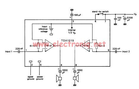
The TDA1519 circuit can deliver 2x6 watts output power. TDA1519 is an integrated class-B dual output amplifier in a 9-lead single in-line (SIL) plastic medium power package primarily developed for car radio applications. The TDA1519 is a robust integrated circuit...
This schematic is an improved version of the Pro Maniac Guitar tube power amplifier. The improved version of the Pro Maniac Guitar tube power amplifier features several enhancements aimed at increasing performance, reliability, and sound quality. The schematic typically includes...
The G9 project is an adaptation of the Gyratec IX dual microphone/line/DI preamplifier, tailored to meet the demands of DIY enthusiasts. A thorough search did not yield a complete design for a tube microphone preamplifier, prompting the decision to...
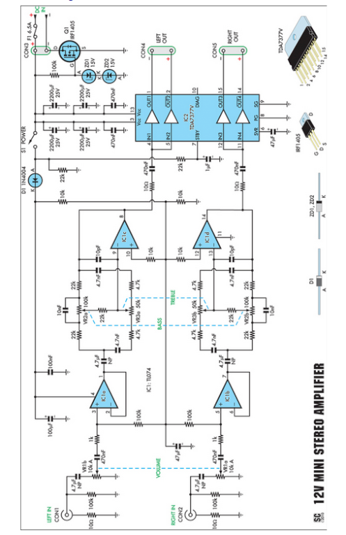
Amplifiers that operate on 12V DC typically do not deliver significant power and are often not classified as high-fidelity (hifi) devices. However, this compact stereo amplifier meets the power requirements effectively. This compact stereo amplifier is designed to operate efficiently...
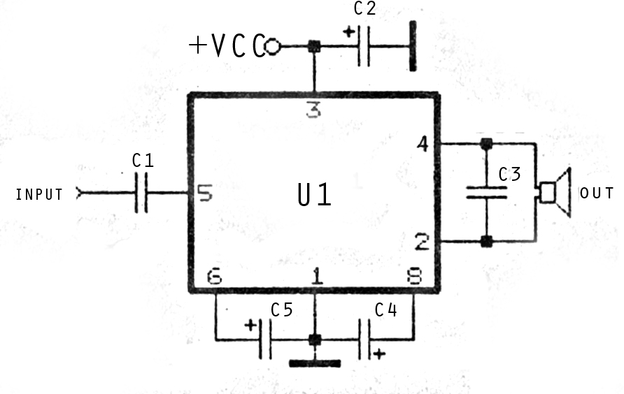
The image above depicts a miniature audio amplifier that is quite simple in design. A schematic for this audio amplifier is provided, which requires only a few components, as detailed in the accompanying diagram. This amplifier is inexpensive to...