
Proximity detector schematic

The proximity detector circuit operates by leveraging the NE567 tone decoder, which is pivotal in detecting frequency shifts caused by changes in capacitance. The circuit is initiated when an object approaches the sensor, resulting in an increase in capacitance due to the proximity of the object. This change in capacitance alters the frequency of the signal detected by the NE567.
The NE567 is configured to respond specifically to a 100 kHz tone, which is generated by an oscillator circuit integrated within the device. The presence of an object modifies the capacitance, effectively shifting the frequency of the signal. The Q1 and Q2 transistors, configured in a common-emitter arrangement, serve as amplifiers to boost the output signal from the NE567. This amplification is crucial for ensuring that the signal is strong enough to activate the subsequent components of the circuit.
LED1 acts as a visual indicator, illuminating when the NE567 detects the appropriate frequency shift, confirming the presence of an object within the sensing range. The circuit may also include additional components such as resistors and capacitors to stabilize the operation of the transistors and the NE567, ensuring reliable performance in various environmental conditions.
Overall, this proximity detector circuit is a straightforward implementation of electronic principles, providing a practical solution for applications requiring object detection without physical contact. Its simplicity and effectiveness make it suitable for educational purposes as well as potential integration into various electronic systems.A very simple proximity detector electronic project can be designed using this schematic circuit. This proximity detector electronic project use a tone decoder integrated circuit ( NE567 ) that will provides a signal with a frequency about 100Khz. When an object is placed near the sensor, the capacitance between sensor is increased. The Q1 and Q2 transistors will amplify the signal and fed it to the NE567 IC, that will make the LED1 to glow. 🔗 External reference
Related Circuits

This circuit appears intriguing, and there is an intention to simulate and construct it; however, clarification is needed regarding the meaning of the three symbols in the circuit (one for audio input, one in the middle, and one at...
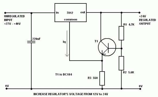
It is often necessary to configure a voltage regulator integrated circuit (IC) to provide a higher output voltage than that established by the regulator alone. One method to achieve this is by connecting the common terminal to the midpoint...
A circuit designed to detect the interruption of a light beam. The initial circuit was a light/dark detector using a photoresistor, which, while capable of detecting light interruptions, suffered from significant interference due to ambient light. This led to...

The complete hardware schematic of the Night Light Saver V6.0 includes an AC line protected by a 1A fuse (F1). Any short circuit caused by the components of the saver will blow the fuse. Resistor R1 and capacitor C1...

This circuit generates sine and square wave signals with frequencies ranging from below 20 Hz to above 20 kHz. The advantage of this circuit diagram is that the output frequency can be adjusted by varying the variable resistor R6. The...

The EtherSmart Wildcard is based on the Lantronix Xport Ethernet device server, which is integrated into an RJ-45 connector housing. The Xport communicates data through a serial UART-USART interface, while the Wildcard bus operates as a parallel interface. A...