
Mixing AC and DC power in a circuit
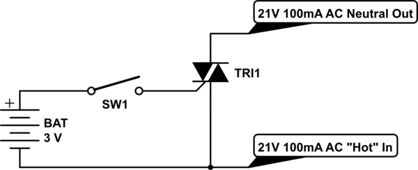
The circuit design involves controlling a furnace using a microcontroller that operates at 3.3V. The furnace is powered by a 21V AC source, which is connected to two output lines designated for Fan and Heat. The TRIAC acts as a switch to control the flow of current to the furnace components, allowing the microcontroller to manage operation effectively.
In this setup, the microcontroller sends a control signal to the gate of the TRIAC, where a +3V signal will turn the TRIAC on, allowing current to flow through the furnace, while a 0V signal will turn it off. However, mixing AC and DC power sources raises significant safety concerns. The connection of the DC battery's negative terminal to the AC "hot" line can lead to unpredictable behavior, including potential battery damage, excessive drain, and circuit failures.
To mitigate these risks, it is advisable to incorporate isolation techniques. An opto-isolated solid-state relay (SSR) can be employed to separate the microcontroller's low-voltage control circuit from the high-voltage AC circuit, ensuring safe operation. Opto-isolators provide the added benefit of preventing high voltage from affecting the microcontroller, thus enhancing overall circuit reliability.
When using TRIACs, it is important to consider their triggering behavior, especially when driven by unipolar DC signals. The 2N6071 TRIAC, for example, requires a specific gate current to ensure reliable conduction. In scenarios where the AC voltage could be hazardous, the use of opto-isolated components is strongly recommended.
Given the low AC voltage of 21V, designing a gate drive circuit that utilizes power from the AC line may introduce complications, such as voltage drops and insufficient gate current. Therefore, a relay-based approach may be more effective, particularly in applications where safety and reliability are paramount. This design choice can help ensure that the furnace operates safely while minimizing the risk of circuit damage or battery failure.Control a furnace using a 3. 3V microcontroller. The furnace operates by connecting a common 21V AC "hot" line to one of two AC "neutral" output lines: Fan and Heat. When connected they have relatively low current flow, ~100mA. I`ve had some success using a TRIAC to do the switching - but I`m directly mixing the power sources by conne
cting the DC battery negative to the common AC "hot" line. Battery negative/hot then becomes the reference at the TRIAC`s MT1, and I can switch the furnace on and off by sending +3V or 0V to the TRIAC base. Question is, is it kosher to mix power sources like this Do I risk an exploding battery, excessive battery drain, weird circuit behavior or anything like that If so, what would be the proper way to do this, to isolate the circuits I have no clue, but google shows some circuits setup in this manner.
I`ll let someone else give an answer to that. My question to you though, why no go for isolation and use a opto-isolated ssr or triac, and not bother mixing them at all Passerby Apr 2 `13 at 4:19 Don`t know too much about the opto-isolated options out there - photo-triacs and SSRs look promising though, thanks for the tip. The few SSR`s I had come across before were all high-voltage types. QuadrupleA Apr 2 `13 at 4:29 Many household-grade thermostats use low holding current mechanical relays for this purpose.
I`ve always been amazed that they can maintain several years of battery life with this approach, but they do. I`d expect a triac would be cheaper, so perhaps there are surge or mis-wiring risks inherent in such applications.
HikeOnPast Apr 2 `13 at 5:20 Some triacs, when controlled from a unipolar DC to the gate with respect to MT1, won`t always conduct when the AC cycle goes negative i. e. they`ll trigger during the positive cycle and reset as the voltage falls through 0V and won`t retrigger again until the next positive cycle.
The 2N6071 I have used before and this was OK - with unipolar DC control on gate the triac was basically equivalent to a closed contact. Gate current needed to activate (say) the 2N6071A will need to be in excess of 10mA so this is a consideration to how you drive the gate from a MCU pin (quadrant IV is always the worst culprit for triggering with any triacs it seems).
2N6071B needs 5mA to guarantee conduction 360. If there is any doubt about the AC voltage possibly being at unsafe levels (i. e. connected to incoming main AC power) I`d use an opto triac circuit to isolate. BUT, with such a small working AC voltage (21Vac) trying to "manufacture" a gate drive circuit that "steals" power from the AC means volts dropped in driving the load. So, given all this I`d probably go for a relay drive circuit unless you are totally happy that the AC you are switching is reasoably isolated from the incoming main AC
🔗 External reference
Related Circuits
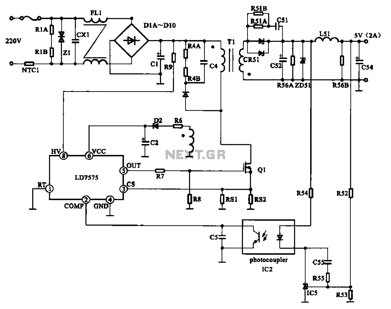
The AC adapter circuit is designed for portable digital products, converting low voltage DC into 220V AC. It features a circuit configuration for a switch power drill utilizing the oscillation IC LD7575 as a switch. This IC operates after...
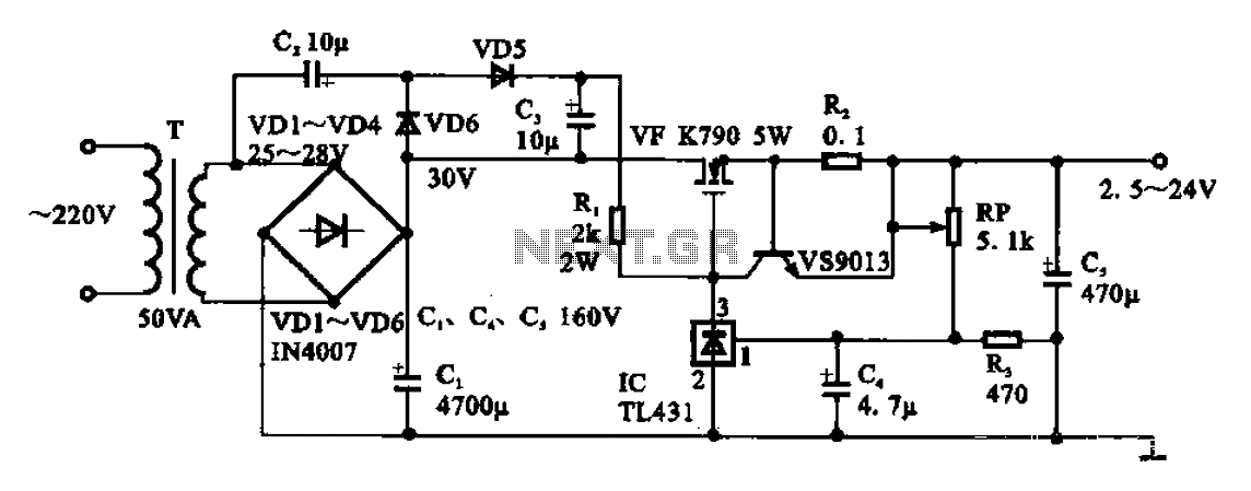
An adjustable DC power supply circuit is presented, consisting of a step-down transformer (T), a rectifier bridge (VD1 to VD4), and additional components. The voltage regulator circuit includes an adjustment potentiometer (RP, 5.1 kΩ), allowing the output voltage to...
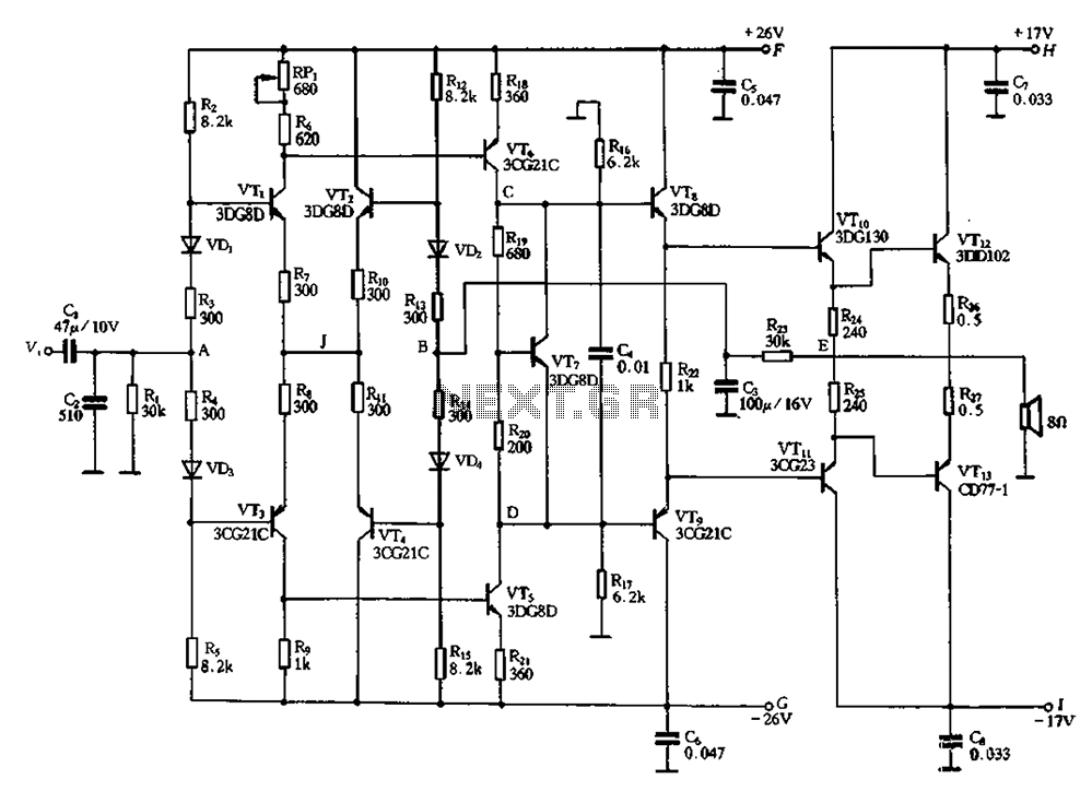
Almost all DC amplifier circuits are utilized as the input stage of differential circuits. Many complementary symmetry circuits also employ a double differential complementary sub-circuit along with a constant current source for the input stage. The constant current source...
This circuit triggers an alarm when its LDR (Light Dependent Resistor) sensor is exposed to light from the sun or a lamp. A 555 astable multivibrator is utilized to generate a tone of approximately 1 kHz upon detecting light....
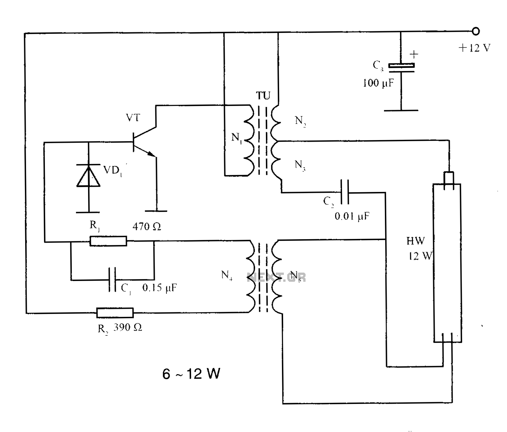
The lighting inverter circuit is designed for 6 to 12W fluorescent lamps. It operates by first bucking the mains voltage, followed by rectification and filtering to charge a battery. When the inverter is activated, it generates a high-frequency alternating...
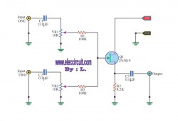
This circuit is a simple mixer circuit that can mix two signal channels into one output channel. It utilizes a codec circuit to convert stereo audio into mono audio. Additionally, the circuit can increase the number of channels by...