
mobile nicd charger
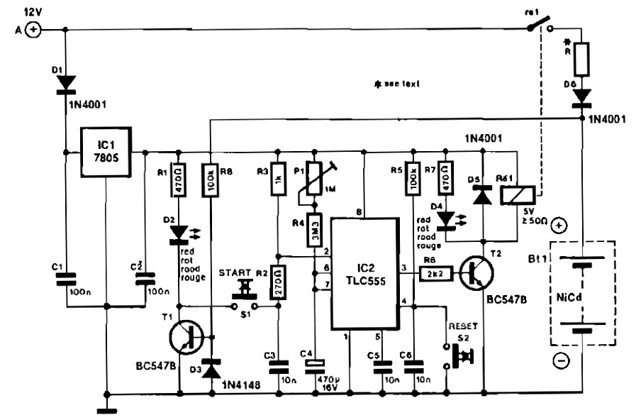
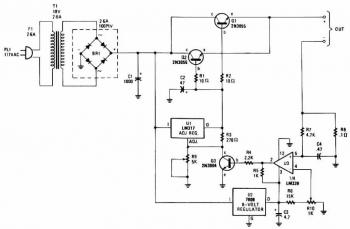
The NiCd charger circuit operates by ensuring proper polarity connection of the NiCd battery to be charged. The use of diode D2 serves as an indicator that confirms the correct connection; it will only illuminate if the battery is connected correctly. This is crucial for preventing potential damage to the battery or the charger circuit itself.
Transistor T1 plays a significant role in the operation of the circuit. It is connected to the base via resistor R8, which allows for a small base current to control a larger collector-emitter current. The design ensures that even when the NiCd battery is fully discharged, it still provides sufficient voltage to activate T1, thereby allowing the circuit to function and indicating this with D2.
The circuit's design highlights the importance of polarity in battery charging systems. If the battery is connected in reverse, T1 will not turn on, and D2 will remain off, thereby protecting the circuit from potential damage. The inclusion of R8 is essential, as it limits the current flowing into the base of T1, ensuring that the transistor operates within safe limits.
Overall, this schematic is a practical implementation for charging NiCd batteries from a car battery source, demonstrating efficient design principles and safety measures that are critical in battery management systems. Further details regarding the power supply and its components can be found on the referenced page, which provides additional context and explanations related to the charger circuit's operation.When the Nicd charger circuit is connected to the car battery, D2 lights only if the Nicad to be charged has been connected with correct polarity. For that purpose, the + terminal of the Nicad battery is connected to the base of T1 via R8. Because even a discharged battery provides some voltage, Ti is switched on and D2 lights. The schematic diagr am come from circuit: Mobile NiCd Charger power supply. Go to that page to read the explanation about above power supply related circuit diagram. 🔗 External reference
Related Circuits
Timer for Charger Circuit Diagram. This timer circuit assists in maintaining the battery in optimal condition by enabling automatic charging for 5 to 6 hours daily, allowing the device to be left unattended. The timer circuit for the charger is...
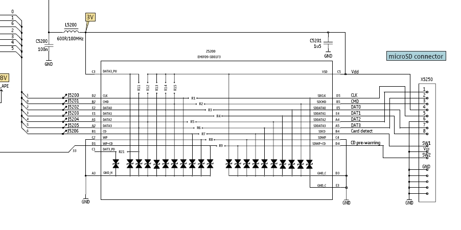
In this tutorial, the functioning of the memory card circuit in mobile phones will be explored. The previous post discussed the pin-outs and types of memory cards utilized in cellular devices. The accompanying block diagram illustrates how the removable...
The Ultra Fast Battery Charger for Nickel-Cadmium (NiCad) battery cells is designed to efficiently charge NiCad batteries. This charger, referred to as the Ultra Fast NiCad Battery Charger, is capable of rapidly filling NiCad battery cells. The charger is...
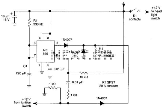
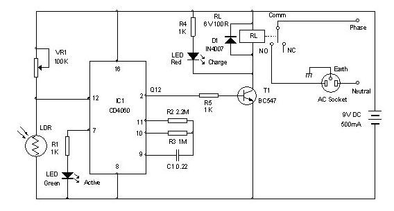
When the ignition switch is activated, relay K1 receives continuous power, allowing the headlights to be turned on. When the ignition is turned off, timer IC1 is activated, maintaining its power for a duration determined by resistor R1 and...
When a discharged gel cell is connected, the charger goes into a fast charge mode at a fixed rate of 400 ma. After the chip detects the voltage leveling off or when 4 1/2 hours has elapsed (whichever happens...
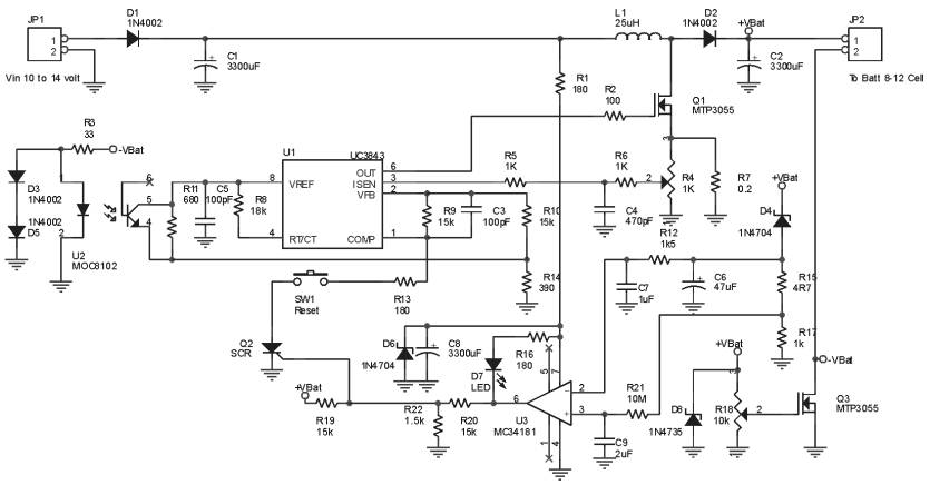
The charger is capable of charging a single cell or multiple series-connected cells with a maximum voltage of 18V. Power transistors Q1 and Q2 are configured as series regulators to manage the output voltage and charging current of the...