
mobile robot schematics

The mobile robot schematic diagram is designed for operation via a cellphone interface, utilizing several key components to facilitate control and movement. The DTMF (Dual-Tone Multi-Frequency) decoder, specifically the MT8870 or CM8870, serves as the primary interface for receiving commands from the cellphone. This decoder interprets the DTMF signals generated by the cellphone keypad, converting them into corresponding digital signals that can be processed by the microcontroller.
The microcontroller at the heart of this system is the ATMEGA16, which is responsible for interpreting the output from the DTMF decoder and executing the appropriate control logic. It processes the signals received and determines the actions that the robot should perform, such as moving forward, backward, or turning.
To drive the robot's movement, a motor driver, specifically the L293D, is employed. This component acts as an interface between the microcontroller and the DC motors, allowing the low-power signals from the microcontroller to control the higher-power motors effectively. The L293D can drive two DC motors simultaneously, providing the capability to control the direction and speed of the robot's movement.
The actuators used in this mobile robot are DC motors rated for 5-6V. These motors convert electrical energy into mechanical energy, enabling the robot to move. The selection of these motors is crucial as they must provide adequate torque and speed for the intended application, ensuring the robot can navigate effectively.
Overall, this schematic diagram integrates these components to create a functional mobile robot that can be controlled remotely via a cellphone, showcasing the synergy between telecommunications and robotics.Mobile robot schematic diagram for cellphone controlled robot. Detail module used for cellphone controlled mobile robot: DTMF Decoder: MT8870/CM8870 ; Microcontroller: ATMEGA16 ; Motor Driver: L293D ; Actuator: DC Motor 5-6V 🔗 External reference
Related Circuits
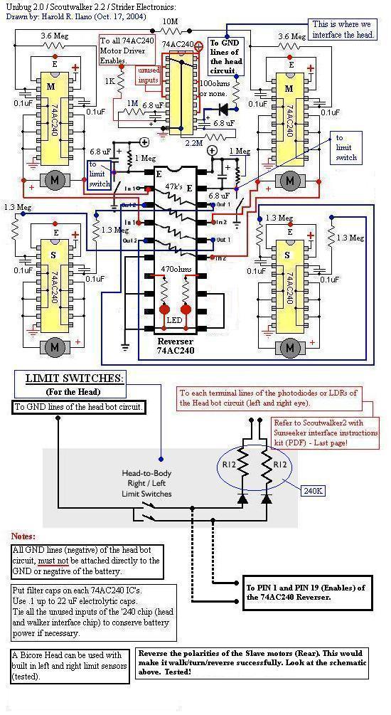
This is an attempt to create a simple and compact photovore. Although it may not be visually appealing, it serves as a good starting point for beginners. It is a personal version of the Dozer photovore. The latest robot...
The TDA2005 integrated circuit (IC) features a high output power of 10W per channel (stereo) at a load of 2 ohms with a distortion of 10%, and 20W in bridge mode at a load of 4 ohms with a...
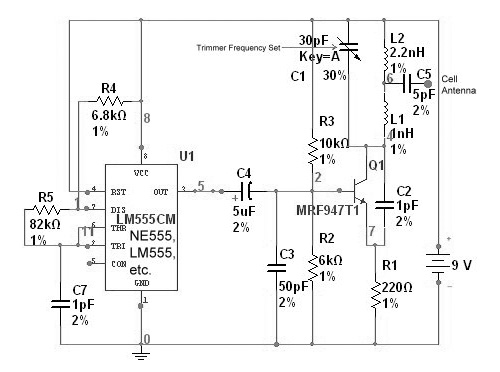
The circuit is based on the NE555 timer, functioning as a simple noise maker, with its output connected to a single transistor oscillator. This oscillator is designed to operate within a frequency range of 800 MHz to 2 GHz,...
A light-seeking solar-powered tiny robot based on a BEAM design. The article includes pictures, links, a video, and a schematic. The described robot employs a BEAM (Biology, Electronics, Aesthetics, and Mechanics) design philosophy, which emphasizes simple, efficient, and often analog...
The individual has been engaged in garden railroading for just over a year, utilizing skills from various hobbies. They have designed and built two scratch-built bridges and nearly 100 trestle bents to support a 200-foot main line. Their interests...
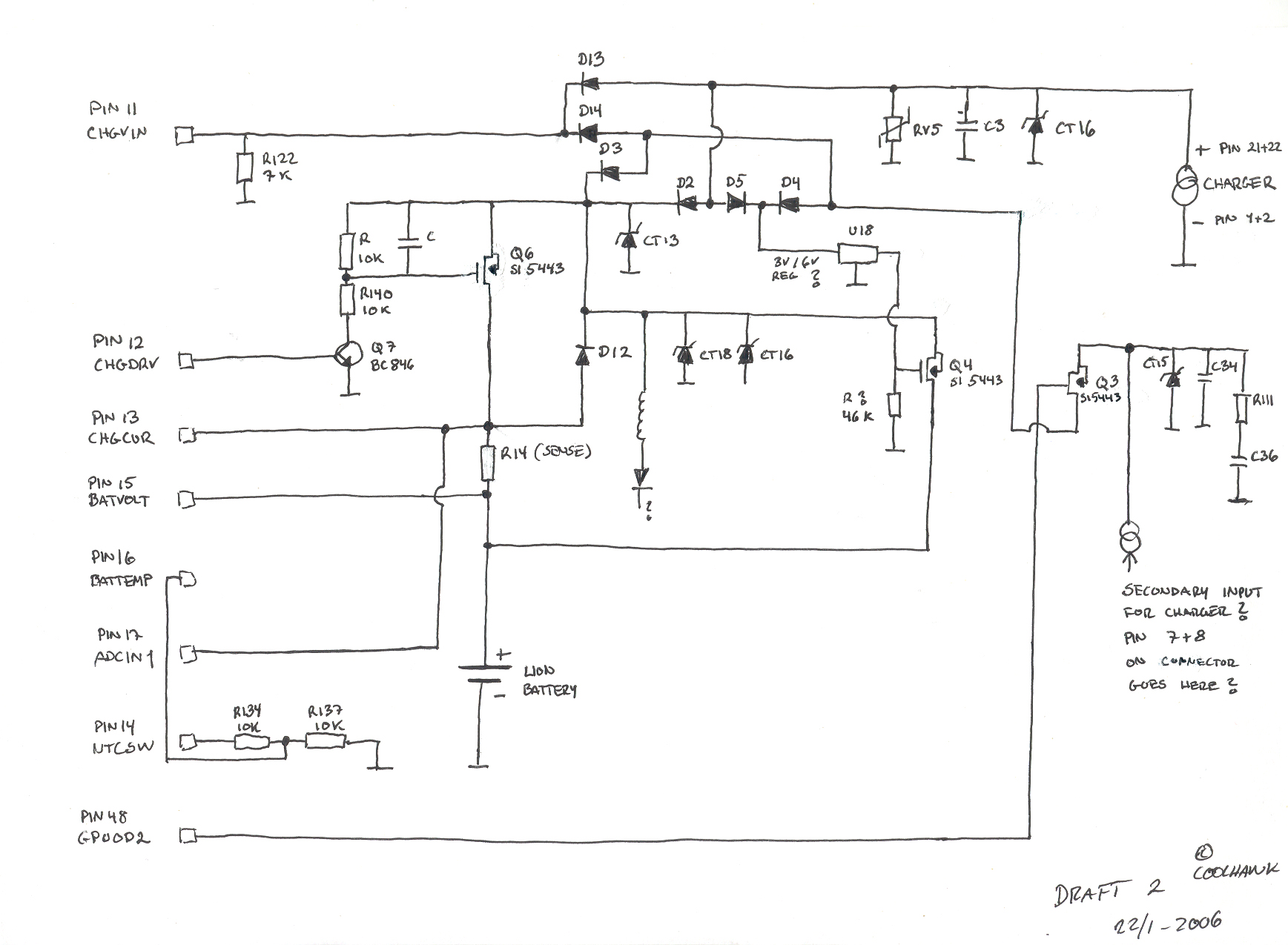
This is a basic hand-drawn schematic version 2. It will be transferred to Protel later when time permits. However, it provides a useful overview of the circuit, which can be charged from two different sources: USB or a standard...