
Offset + 2% - temperature coefficient temperature compensation circuit

The LM3sDZ temperature detection circuit is designed for ease of use and functionality in temperature measurement applications. The circuit operates with a temperature range starting from 0°C and extending up to a defined upper limit, producing an output voltage that correlates with the temperature changes. The output voltage is configured to vary from 0 to 500mV, which is a common range for temperature sensors that interface with microcontrollers and other electronic devices.
The operational amplifier (OP) plays a crucial role in amplifying the sensor output. The circuit employs a gain of 10, achieved through careful selection of resistor values. This amplification allows for a more significant voltage output, which enhances the resolution of the temperature reading. The division circuit further processes the amplified signal, allowing it to output a voltage range of 0 to 10V, suitable for various applications.
However, it is essential to note that the circuit's performance may be affected when the temperature approaches 1°C, as the output may saturate, leading to inaccurate readings. To mitigate this issue, a reference magnification ratio of 1:5 to 1:6 is recommended, which helps maintain the linearity of the output in relation to the temperature changes.
The calculation formula for the division circuit indicates that the output voltage is a function of the input voltage and the set magnification. This relationship is critical for users who may need to adjust the circuit for specific temperature ranges or applications. For instance, when the magnification is set to 1, the circuit can adequately handle temperatures around 25°C with a reference voltage of 5V.
In scenarios where multiple changes in temperature are anticipated, it is advisable to adjust the magnification accordingly to ensure that the output remains consistent and accurate. The input voltage range is specified to be between 3V and 6V, which aligns with the operational capabilities of the circuit. As the input voltage changes, the output will reflect these variations, providing real-time temperature readings.
Overall, the LM3sDZ temperature detection circuit offers a practical solution for temperature monitoring, with considerations for amplification, output range, and operational stability. Proper adjustments and configurations can enhance its performance, making it suitable for various applications in electronics and temperature sensing. Circuit of the easy to use cedar LM3sDZ temperature detection heir. Does not show adjusted to obtain 1 (hnV/aC output temperature change range if he is 0 ~ so * c, -. The outpu t is 0 ~ 500mV, 4t amplifier OP is 10 times magnification (by the R., the island as scheduled ) after the 0 to ten sVo in the division circuit, near ov can not serve as the denominator saturated output shaft 1-c), so as to 2sc reference magnification of 111-5 to 1-6 Lin. According to the calculation formula for dividing circuit, Ray. 10z/- x, + a stone ioW when. Magnification of l, hindered terms of a three 5V, 2S oC :: crab benchmark amplification. If you make multiple should 2b magnification in 1.5 3 the same change; x Jing input voltage range of a 3, 3V ~ 6-60v mouth Accordingly, Shall be thrown OP spin big clamor As the sV voltage is changed to 3.33V, its magnification is less than l, at 250C base temperature with y ugly with the 43-phase input voltage Confidence - svt
Related Circuits
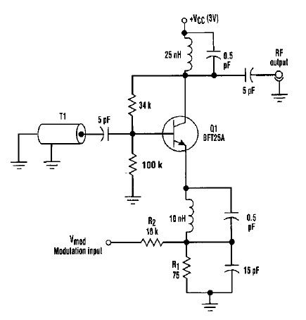
This varactorless high-frequency modulator electronic project must be powered by a simple DC 3-volt power source, such as a 3-volt battery. Traditionally, high-frequency oscillators are frequency-modulated using a varactor. However, varactors typically require a significant voltage change to achieve...
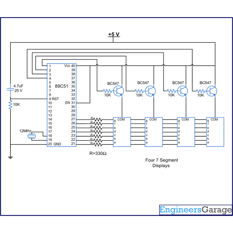
A digital clock displays time in a digital format. The circuit outlined here shows the time with double-digit minutes and two digits for seconds across four seven-segment displays. The segments of the displays are interconnected with the 8051 microcontroller...
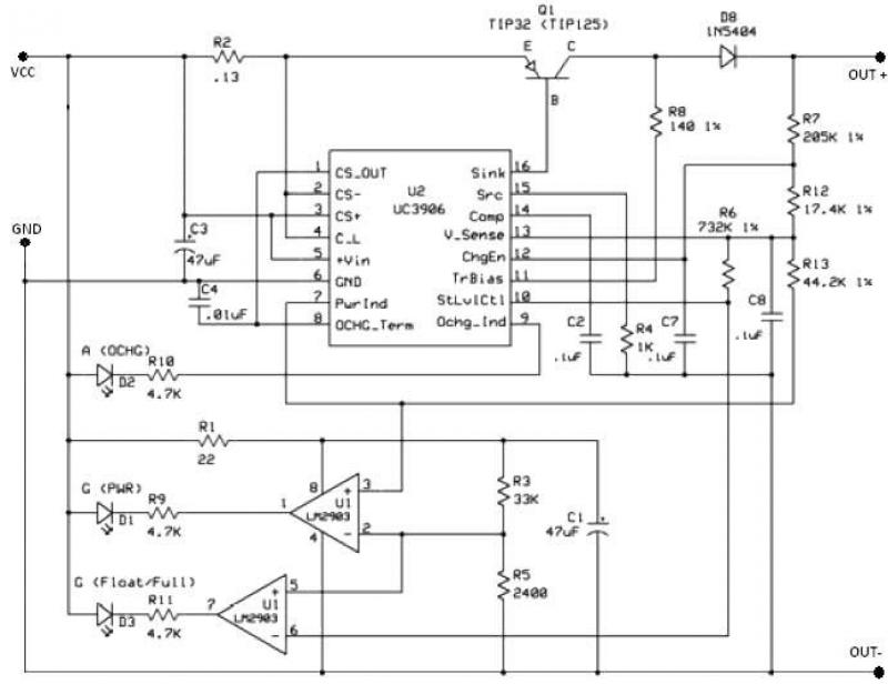
The UC3906 battery charger circuit controller includes all necessary circuitry to manage the charge and hold cycles for sealed lead-acid batteries. This circuit is specifically designed to deliver the appropriate charging voltage and current based on the battery's temperature...
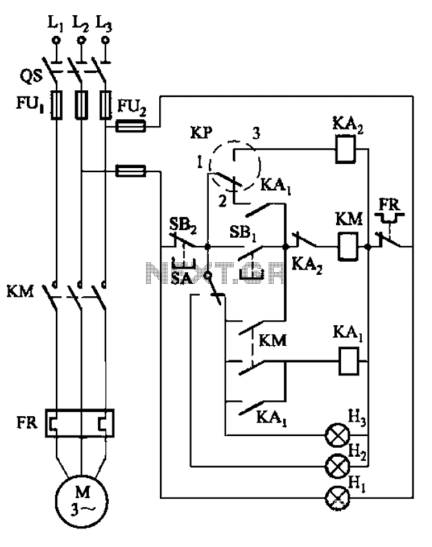
An air compressor is commonly utilized in electrical equipment factories and is typically controlled by electrical contacts. The circuit diagram is depicted in Figure 5-1. The circuit allows for both automatic and manual operation. In the diagram, KP represents...
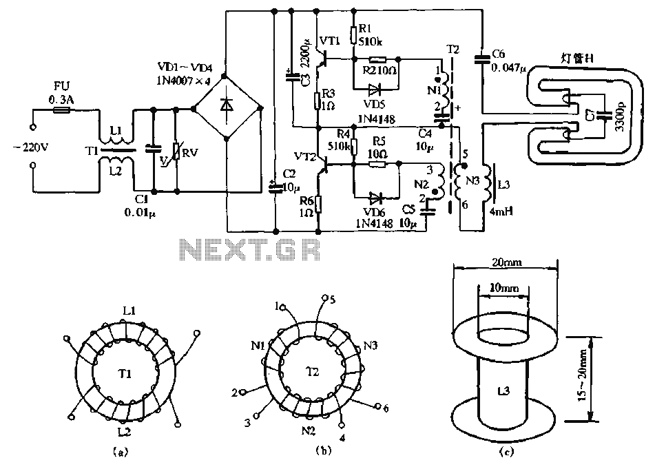
The circuit diagram illustrates a dedicated electronic ballast circuit for a 16W2D single-ended energy-saving lamp. The RFI filter circuit consists of components such as zinc oxide varistors for protection, bridge rectifiers, a high-frequency oscillator, and an LC series output...
Constantly changing light and sound analog controller circuit 07 The circuit described is an analog controller designed to modulate light and sound in a dynamic manner. This circuit utilizes various electronic components to create an interactive experience where both light...