
Model rocket launcher

The circuit operates on a straightforward principle where the launch timer is initiated by a power supply connected to the integrated circuit. The countdown mechanism is visually indicated through a series of LEDs, which light up sequentially. The final LED activation triggers a transistor, which in turn activates a relay responsible for completing the circuit to the launch pad. The design incorporates resistors and capacitors to ensure precise timing and LED brightness, enhancing the user experience while maintaining safety protocols.
To ensure safety during operation, the automatic-off timer is critical. Once the launch sequence is complete and relay RY2 opens, the interruption of current to transistor Q2 is designed to prevent any accidental ignition of the rocket. The combination of resistor R2 and capacitor C4 provides a delay, allowing for a brief continuation of current flow before the system fully shuts down, ensuring that any residual energy is safely dissipated. The circuit's reset and launch initiation features are designed for ease of use, allowing the operator to reset the countdown or manually engage the relay as needed.
Overall, this circuit design effectively balances functionality, safety, and user interface, making it suitable for controlled rocket launches. The components are selected to provide reliable performance, and the schematic layout should reflect clear connections between each element, ensuring that the circuit can be replicated or modified as required.The circuit consists of the launch timer itself and an automatic-off timer. When power is applied to that IC, the countdown LED's sequence is on until they are all lit. When the last one LED1, is fully lit, transistor Ql saturates, energizing RY2. When that happens, a circuit between the lantern battery at the launch pad and the nickel-chromium wire is completed; the wire heats up as before, and the rocket is launched. Resistor R4 and capacitor C3 determine the countdown timing; with the values shown it should be approximately 10 seconds.
Resistors R3 and R5 set the LED brightness. Safety is of the utmost importance. That's the purpose of the second half of the circuit. When RY2 opens, the current flow to Q2 is disrupted. But, because of the presence of R2 and C4, the transistor remains saturated for about 3 seconds. After that, however, the transistor stops conducting and RY1 is de-energized. That cuts off the power to the rest of the circuit, and RY2 de-energizes again, breaking the circuit to the launch pad. Switch S3 is used to reset the countdown. Once that is done, pressing Si starts the launch sequence; the rest is automatic. Switch S4 is used to latch RY1 manually if needed.
Related Circuits
Multisim is circuit simulation software based on SPICE, which stands for Simulation Program with Integrated Circuit Emphasis. Developed in 1975 at the University of California, Berkeley, it focuses on simulating integrated circuits. In Multisim 9, the MultiMCU module must...
There are two independent modeling light circuits for the P2000D, one for each of the two channels. The modeling light circuit is completely separate from the high voltage strobe circuitry, even featuring its own On/Off switch. Therefore, the functionality...
Model aircraft pilots utilize PC flight simulator software to practice handling model aircraft without risking damage to real models. It is advantageous to use the actual model aircraft remote control (RC) as the input device for the software, necessitating...
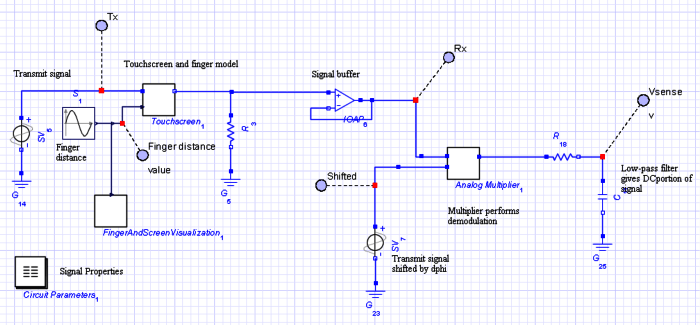
The objective of this project is to develop a model of a capacitive touch screen, which includes the physical modeling of a user's finger, the materials of the touch screen, and the touch-detection circuitry. A capacitive touch screen functions...
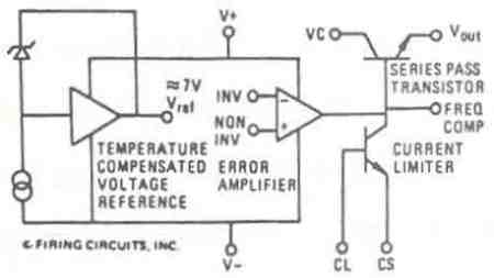
This manual applies to all integral horsepower DC motor controls within this series, ranging from 40 HP to 300 HP. The integrated circuit regulator selection of these DC motor controls is modular in construction, allowing for minimal downtime in...
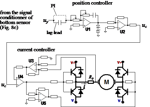
Typical solutions for the vertical movement of probes in bed profiling devices include guide wheels, dumpers, brakes, and vibration suppressors (not shown). A complete mechanism for vertical motion of a bed profiler is illustrated, featuring an electric motor, a...