
Coincidence Detector for Logic Signals

The coincidence detector circuit is designed to identify when two input signals, A and B, are simultaneously active, indicating a logical coincidence. This functionality is particularly valuable in applications involving complex digital logic systems, where it is essential to monitor multiple conditions or events concurrently.
The circuit typically employs logic gates, such as AND gates, to achieve this detection. When both inputs are high (logic level '1'), the output of the AND gate will also be high, signaling that a coincidence has occurred. Conversely, if either input is low (logic level '0'), the output will be low, indicating no coincidence.
To implement this circuit, two input terminals are connected to the respective inputs of the AND gate. The output terminal of the AND gate is then connected to an indicator device, such as an LED or a buzzer, which activates when a coincidence is detected. The circuit can be powered by a standard voltage source, typically ranging from 5V to 15V, depending on the logic family used.
In more advanced applications, additional features may be integrated, such as debounce circuits to filter out noise or fluctuations in the input signals, and flip-flops to store the state of the coincidence detection for further processing. The design may also incorporate multiple AND gates for detecting coincidences among more than two signals, thus expanding its utility in complex digital systems.
Overall, the coincidence detector circuit serves as a crucial component in various electronic systems, enabling effective monitoring and control of logic states.This is a coincidence detector circuit. This circuit is very useful for monitoring complex logic circuits. This circuit has two inputs, A and B. if A and B are.. 🔗 External reference
Related Circuits
The bat ultrasounds are picked up by the microphone SPKR1 and go through two stages of amplification at Q1 and Q2. Separately, a tunable (R12) single frequency is produced by the LM567 oscillator U1. The LM567 is a tone...
This circuit employs a 1458 dual op-amp to create a radar detector. C1 acts as the radar signal detector. The first op-amp functions as a current-to-voltage converter, while the second op-amp buffers the output to drive the piezo transducer....
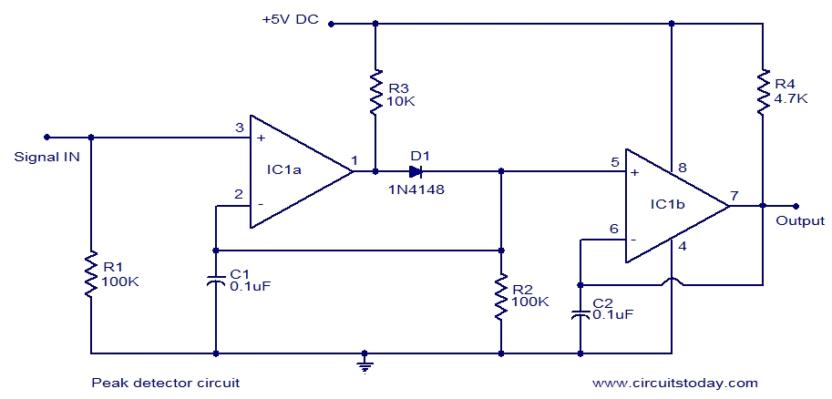
LM339-based peak detector circuit. Simple and easy to construct. Operates from a 5V DC single supply. LM339 is a dual comparator. The LM339-based peak detector circuit is designed to capture and hold the peak value of an input signal. This...
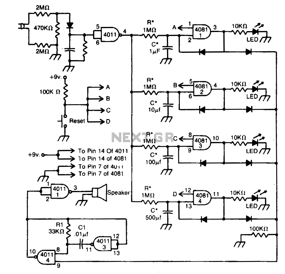
This circuit indicates that a power outage occurred for 1, 10, 100, and 500 seconds based on the values provided for R* and C*. After a power failure, the circuit can be reset by pressing the Reset button. The described...
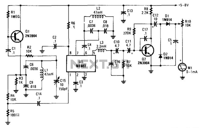
In this circuit, oscillator Q1 operates at approximately 15 kHz and provides input to mixer U1. U1 contains an internal oscillator that also runs at around 15 kHz. Capacitor C15 is employed to achieve zero-beat between both oscillators. When...
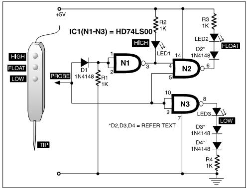
A TTL logic probe is an essential tool for troubleshooting digital circuits. Various methods can be utilized to design a logic probe. The most common designs incorporate operational amplifiers, logic gates (OR, NOT, XOR), and transistors. The circuit described...