
Modern FM Converter
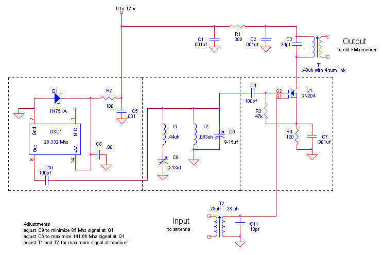
The proposed design features a modern receiving converter tailored for pre-war FM radio sets, which traditionally operate within the 42 to 50 MHz frequency range. The converter utilizes a MOSFET transistor for its amplification and a TTL packaged oscillator for frequency generation, allowing compatibility with contemporary FM stations, such as the chosen frequency of 101.1 MHz.
The circuit begins with the input stage, where the audio signal from the antenna is fed into a bandpass filter, designed to isolate the desired frequency range while attenuating unwanted signals. The filtered signal is then amplified by the MOSFET transistor, which provides the necessary gain to drive the subsequent stages of the circuit.
Following the amplification, the TTL oscillator generates a local oscillator signal at a frequency that, when mixed with the incoming FM signal, produces an intermediate frequency (IF) suitable for further processing. The mixing process can be achieved using a diode mixer or an active mixer configuration, which combines the amplified RF signal with the local oscillator signal to create the IF output.
The IF signal is then passed through another bandpass filter to remove any unwanted harmonics or spurious signals generated during the mixing process. This filtered IF signal is subsequently demodulated to recover the original audio signal. Demodulation can be accomplished using various techniques, such as a phase-locked loop (PLL) or a simple envelope detector, depending on the desired fidelity and complexity of the design.
Finally, the demodulated audio signal is amplified again, if necessary, to drive the audio output stage, which can be connected to the pre-war FM radio's audio input. This entire system allows users to enjoy modern FM broadcasting while utilizing their vintage radio equipment, effectively bridging the gap between historical technology and contemporary audio enjoyment.Here is my design for a modern receiving converter for pre-war FM sets. Accordingly, this article presents a design for listening to present day FM stations on a prewar FM set based on a MOSFET transistor and a TTL (transistor-transistor logic) packaged oscillator. Someone else might have done it with vacuum tubes, but this design suits me fine. It is all a matter of taste. My FM radio station of choice is at 101.1 MHz. I specialize in FM only radios, so listening to this station is no problem on most of my sets. But prior to WWII, the FM radio band covered 42 to 50 MHz. These prewar FM radios are nearly useless. Turn one on 🔗 External reference
Related Circuits
The main ΣΔ loop operates in steady state and is fully controlled by summing comparator Q2. This comparator amplifies the ripples of the sensed inductor current and output voltage with gains KI and KV, respectively, to generate an internal...
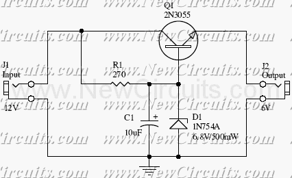
This small but useful circuit is a DC voltage converter for using 6V devices with car battery voltage. The maximum output current is dependent if the T1 is covered with a proper heat sink or not. You can use...
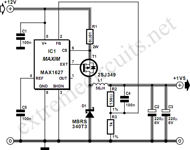
Most small internal combustion engines used in model building utilize glow plugs for starting. However, glow plugs operate at 1.5 V, while components like fuel pumps, starter motors, and chargers typically operate at 12 V. This discrepancy necessitates a...
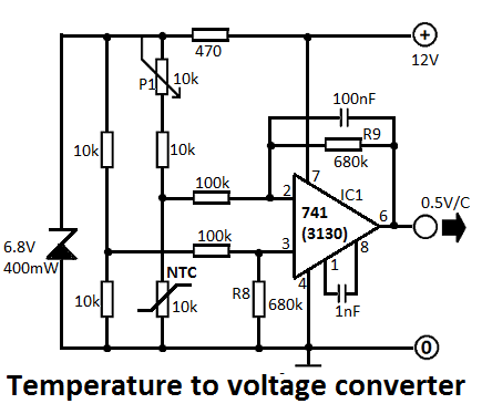
This simple temperature-to-voltage converter circuit allows for precise measurement of room temperature using an NTC resistor or thermistor. The temperature-to-voltage converter circuit typically employs a negative temperature coefficient (NTC) thermistor, which exhibits a decrease in resistance as temperature increases. This...
A 555 timer can be used to generate a square wave to produce a negative voltage relative to the negative battery terminal. When the timer output at pin 3 goes positive, the series 22 uF capacitor charges through the...
A 6V to 12V DC converter circuit is designed to convert a lower voltage of approximately 6 volts to a higher voltage of 12 volts, albeit with a reduced current rating. This inverter circuit can deliver up to 800mA...