
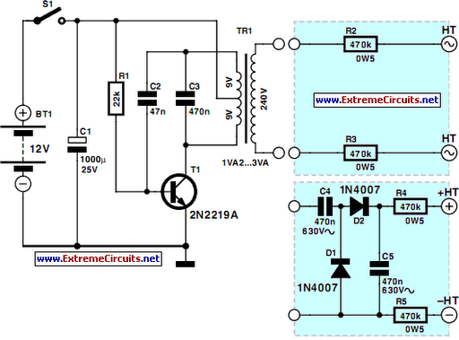
Modified Sine Wave Signal Generator

To design an inverter, various factors must be considered, including the input and output voltage requirements, frequency, power rating, and the type of inverter topology (e.g., square wave, modified sine wave, or pure sine wave). The choice of components, particularly the transformer, is crucial, as it determines the efficiency and performance of the inverter.
Inverters typically consist of several key components: a DC power source (such as batteries or solar panels), a switching circuit (often using transistors or MOSFETs), a transformer for voltage step-up or step-down, and a control circuit that regulates the switching frequency and ensures proper operation.
The switching circuit is responsible for converting the DC input into an AC output by rapidly turning the transistors on and off. The transformer then modifies the voltage level to the desired output. Additionally, the control circuit may include feedback mechanisms to stabilize the output voltage and protect against overload conditions.
Thermal management is another critical aspect of inverter design, as components can generate significant heat during operation. Adequate heat sinks and cooling solutions should be implemented to maintain optimal operating temperatures.
Finally, safety features such as fuses, circuit breakers, and isolation techniques must be integrated into the design to protect both the inverter and the connected loads from potential faults or failures. Overall, a well-designed inverter requires careful consideration of electrical parameters, component selection, and safety measures to ensure reliable and efficient operation.There is a lot you need to know to completely design an inverter. Unless you can acquire a custom made transformer your circuit design is ruled by th.. 🔗 External reference
Related Circuits
This project presents a useful device for the beach, intended to deter individuals from touching personal belongings left on a towel while swimming. It can also be employed in an office or workshop setting. The circuit, compact in size...
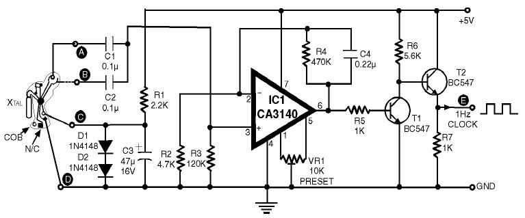
1Hz Clock Generator Circuit with Chip On Board (COB). The COBs used in different watches may differ somewhat in their configuration. However, through trial and error, one can identify the appropriate points corresponding to points A, B, C, and...
The circuit includes 10K resistors at the bases of the transistors and 1K resistors at the collectors. It is essential to retain these components when relocating the transistors, as omitting the 10K resistors could result in transistor failure, and...
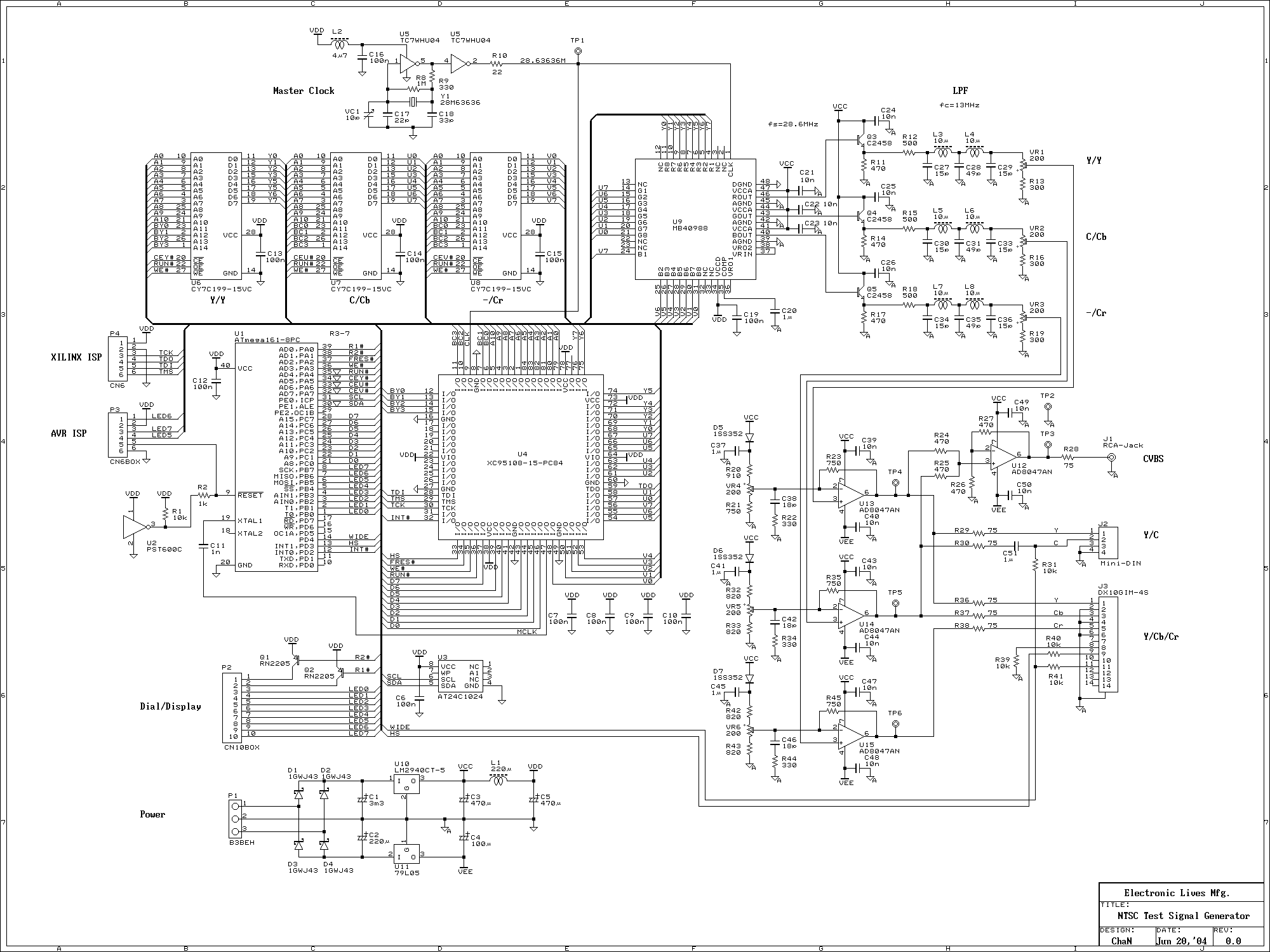
This signal generator uses a three channel DAC to generate Composite video signal (CVBS) and S video signal (Y/C separated) at the same time, left one channel is not used in NTSC format. It is assigned for one of...
Marx Generators are commonly utilized in pulsed power and high voltage applications to produce a high peak voltage pulse. The fundamental principle behind these generators involves charging several capacitors in parallel, followed by closing switches to connect them in...
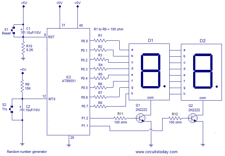
A simple random number generator utilizing the 8051 microcontroller. The AT89S51 is the controller employed in this setup. The circuit design for the random number generator based on the AT89S51 microcontroller involves several essential components and connections. The AT89S51 microcontroller,...