
Modify a 2000-2002 Neons Side Markers to Blink
The proposed modification involves the following steps:
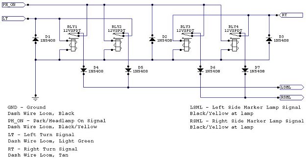
1. **Relay Configuration**: Utilize four relays to achieve the desired XOR functionality. The first two relays will handle the NOT operations, while the remaining two will manage the AND and wired OR functions.
2. **Wiring the Relays**: The relays should be wired such that the first relay takes the input from the parking light signal and outputs to the second relay, which inverts this signal. The third relay will take the input from the turn signal and output to the fourth relay, which combines the outputs of the first two relays.
3. **Diode Protection**: Diodes must be placed in the circuit to prevent backfeeding of current into the inputs, ensuring that the correct signal paths are maintained.
4. **Testing the Circuit**: After wiring, the circuit should be tested to confirm that when the parking lights are off, the side markers blink in correlation with the turn signals. When the parking lights are on, the side markers should turn off when the turn signal is activated.
5. **Reversibility**: The modification should be designed so that it can be easily reversed if necessary, allowing for the original wiring configuration to be restored without permanent alterations to the vehicle's electrical system.
This approach provides an effective solution to enhance the visibility of turn signals on the 2000+ Neon models while maintaining compliance with safety standards and preserving the integrity of the vehicle's electrical system.Because the Neon has inboard mounted turn signals, they are not visible from the side. Typically a manufacturer will mount a second light that is visible on the side or make the side markers blink, as they did on the 9x Neons. However on the North American 2000+ Neons the side markers do not blink and there is no side visible turn signal.
So this is really a safety improvement, so that vehicles and pedestrians at right angles to you can see your turn signals, as they should. The goal in this case is a simple modification to make the side markers blink in correlation with the turn signal, while maintaining their original operation as parking lights.
Also, to make the procedure as minimally intrusive as possible, reversible and easily repeatable. Being that I have a Canadian 2000 Chrysler Neon, it comes factory equipped with Daytime Running Lights (DRLs). For the Neon, this means that the front turn signals serve double duty as DRLs and as a consequence, the only "pure" turn signal signals are in the dash.
(For 2003 the fog lights became the DRLs, not sure if this document applies to those vehicles. ) In addition, the vehicle has been wired such that an unpowered, or unconnected lamp or circuit is simply disconnected and not grounded. All the lamps however are switched on the hot side and continuously grounded on the neutral. (Not that a lamp really has an orientation though. ) So why do I care about grounding Well, because if the hot side were grounded when "off", a standard modification used on other vehicles could be used here.
That is, providing the the turn signal to the neutral side of the lamp, while maintaining the park signal to the hot side. But this does not work in this case. Another option would be to replace the side makers with a dual filament bulb and socket, but I decided against that, as it would require more modifications to the car.
So thus, I`m left with rewiring the hot side of the side marker lamps to provide the signal I want. Basically, I want to merge the "pure" turn signal with the parking lamp signal. When the parking lamps are off, I want the light to illuminate directly in relation to the turn signal. When the parking lights are on, I want the light to blink off when the turn signal illuminates. In digital logic, it is an Exclusive OR (XOR) operation between the two signals. Being automotive power signals I want to switch and not digital voltages, digital logic gates are out.
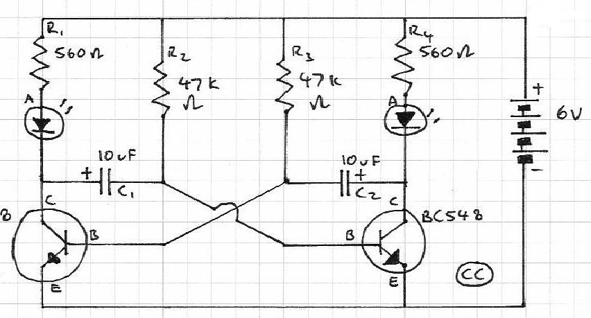
It is possible to construct this out of discrete transistors and such, and it would work great, but the component count and complexity of wiring increases a lot so I decided against this. So, in the end I settled on relays. A relay is an electricially controlled physical switch (or electrically controlled electronic switch in the case of solid state relays).
In relay or ladder logic, as it is sometimes called, a SPDT (Single Pole - Double Throw) relay can perform one of the three basic logic operations, AND, OR and NOT. XOR is formed from its inputs (A, B) as follows: XOR = [A AND (NOT(B)] OR [(NOT(A) AND B]. Breaking that into it`s simplest components, we would need 5 relays (2 NOT, 2 AND, 1 OR) to perform this operation.
Luckily we can simplify. An OR operation can be simplified down to simply a connection of the two inputs directly to the outputs. This works because of the low level operation, if either of the inputs is "on" power flows to the output.
This is called a wired OR and needs to be "fixed" a bit by adding diodes to make sure the power flows in the right direction and not back to the inputs. So, down to four relays. A bit of a jump here, but [A AND (NOT(B)] can be simplified from two down to a single relay. By using A 🔗 External reference
Related Circuits
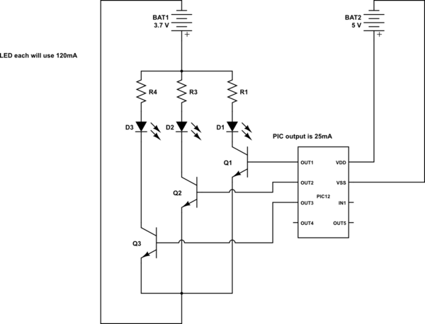
This is a conceptual schema utilizing a PIC12 microcontroller to control the blinking of three LEDs, each exhibiting different blinking patterns. There are several questions that need to be addressed. The circuit design involves a PIC12 microcontroller, which is a...
The purpose of this circuit is to power a lamp or other appliance for a specified duration (30 minutes in this case) and then automatically turn it off. This functionality is particularly useful for reading in bed at night,...
The scope of the AM transmitter is designed to handle amplitude modulated (AM) double sideband (DSB) signals. A standard AM signal consists of a carrier wave and two symmetrically spaced sidebands. The two sidebands carry the same amplitude and...

Daylight shutoff; the schematic has been updated but is not shown here. The daylight shutoff circuit is designed to automatically turn off lighting systems during daylight hours, thereby conserving energy and extending the lifespan of the lighting fixtures. Typically, this...
Blinks 2 LEDs in sequence. An explanation of its operation is requested. It is understood that a capacitor charges, causing the LED to turn off, and when it discharges, the LED turns on. However, clarification on the purpose of...
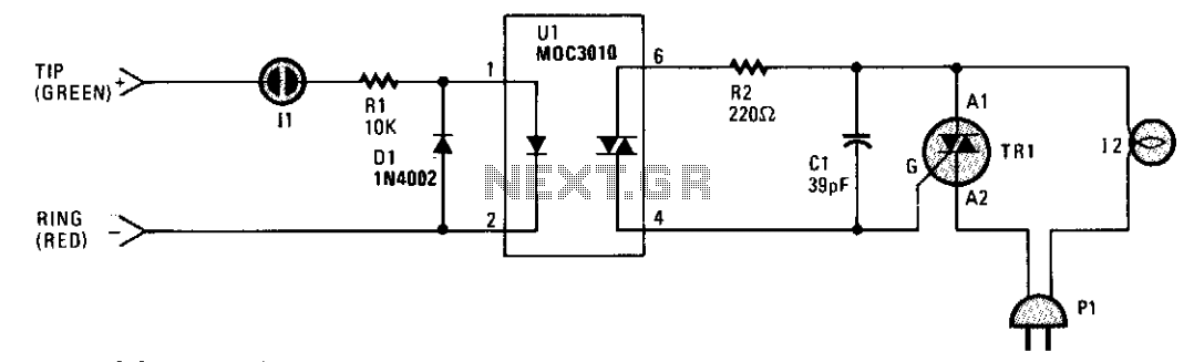
A small neon lamp is activated by the telephone's ringing voltage, allowing a sufficient current to flow to the LED in optocoupler U1. This activation subsequently triggers a 6-A Triac that controls a 117-Vac lamp or bell. Capacitor C1...
Warning: include(partials/cookie-banner.php): Failed to open stream: Permission denied in /var/www/html/nextgr/view-circuit.php on line 713
Warning: include(): Failed opening 'partials/cookie-banner.php' for inclusion (include_path='.:/usr/share/php') in /var/www/html/nextgr/view-circuit.php on line 713