
momentary switch teamed with
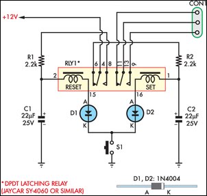
The circuit operates on a 12V power supply and employs a momentary pushbutton switch (SPST) to control a DPDT latching relay. The relay's latching function allows it to maintain its state without continuous power, making it ideal for applications where a temporary button press is preferred to toggle a device on and off. The design minimizes power consumption by ensuring that the relay only draws current during the switching operation.
In the initial state, the relay is reset, and capacitor C2 charges through the resistor R2. This initial charging phase is critical for establishing the necessary voltage across C2 to activate the relay. The discharge of C2 through the relay's coil upon pressing S1 is what triggers the latching mechanism. The diode D2 serves to prevent back EMF generated by the relay coil from damaging other components in the circuit.
As the circuit transitions from the reset to the set state, C1 charges through R1, which is essential for maintaining the relay's state until the button is pressed again. The timing and responsiveness of the circuit can be fine-tuned by adjusting the values of R1 and R2, as well as the capacitance of C1 and C2, depending on the specific relay characteristics used.
The versatility of this circuit allows for various applications beyond automotive use, including household appliances and industrial controls, where a momentary switch is preferred for toggling operations. The unused relay contacts provide additional functionality, enabling the circuit to control other devices or indicators as needed, making it a flexible solution for various electronic design requirements.This circuit allows an SPST momentary pushbutton to act as a push-on push-off switch, using a DPDT latching (bi-stable) relay. It was originally intended to allow a single pushbutton switch on the dash of a vintage car to provide a latched function.
The relay only draws current when it is being switched. At other times, the only current drain on t he 12V supply is the leakage current of one 22 µF capacitor, which is very low. It works as follows. Assume that initially the latching relay is in the reset state, with pins 4 and 6 connected together. In this state, C2 charges up to +12V via 2. 2kO resistor R2 while capacitor C1 remains discharged as it is not connected to the 12V supply. If S1 is pressed, C2 discharges via the relay`s set coil, diode D2 and S1. This switches the relay into its set position, connecting pins 4 and 8. C1 then begins to charge via R1. While S1 is being held down, the relay does not return to the reset position because the current supplied via R1 is insufficient for the coil to latch the armature.
As soon as S1 is released, current no longer flows though the coil so C1 can finish charging, ready for the next button press. Once the relay has switched and C1 has finished charging, pressing S1 again causes the relay to switch back to the reset state via the same process.
The unused set of relay contacts can be used as an SPST or SPDT switch. The circuit as shown has been tested with the Jaycar SY4060 relay. It will work with other DPDT twin-coil latching relays but the resistor and capacitor values may need to be adjusted to suit. Relays with lower resistance coils will need larger value capacitors and smaller value resistors. 🔗 External reference
Related Circuits
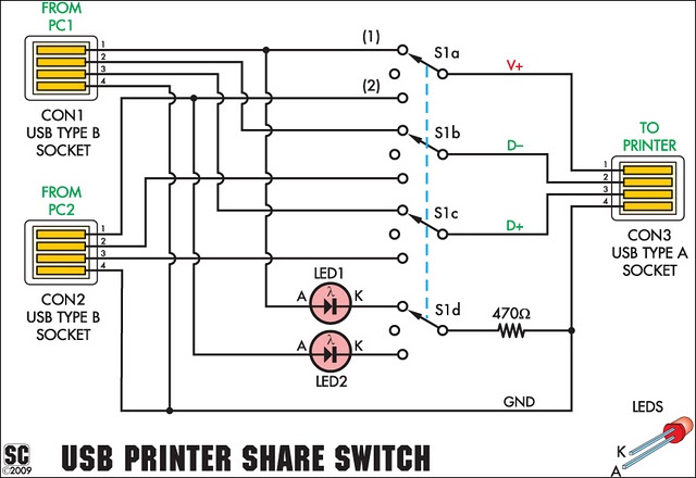
This simple device enables two computers to share a single USB printer or other USB devices, such as an external flash drive, memory card reader, or scanner. A rotary switch is used to select the PC that will be connected...
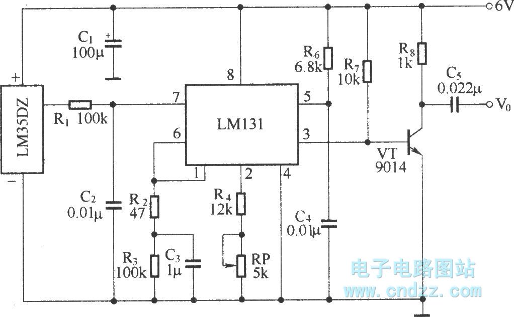
The circuit depicted in the figure integrates a temperature detection system, a temperature-voltage switch, and a voltage-frequency switch to enable remote temperature monitoring. This circuit is connected to a wireless transmission circuit, creating a remote control temperature detection system....
This is an ultrasonic motion detector circuit with high movement sensitivity. It can detect even minor air movements, such as hot air rising or wind blowing, when the trimpot is adjusted to a sensitive position. The transmitter emits a...
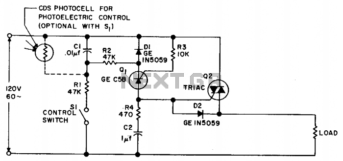
Synchronous switching activates only when the AC supply voltage crosses zero and deactivates only when the current reaches zero. This circuit responds to either a mechanical switch or a variable resistance, such as a cadmium-sulfide photocell. It minimizes disturbances...
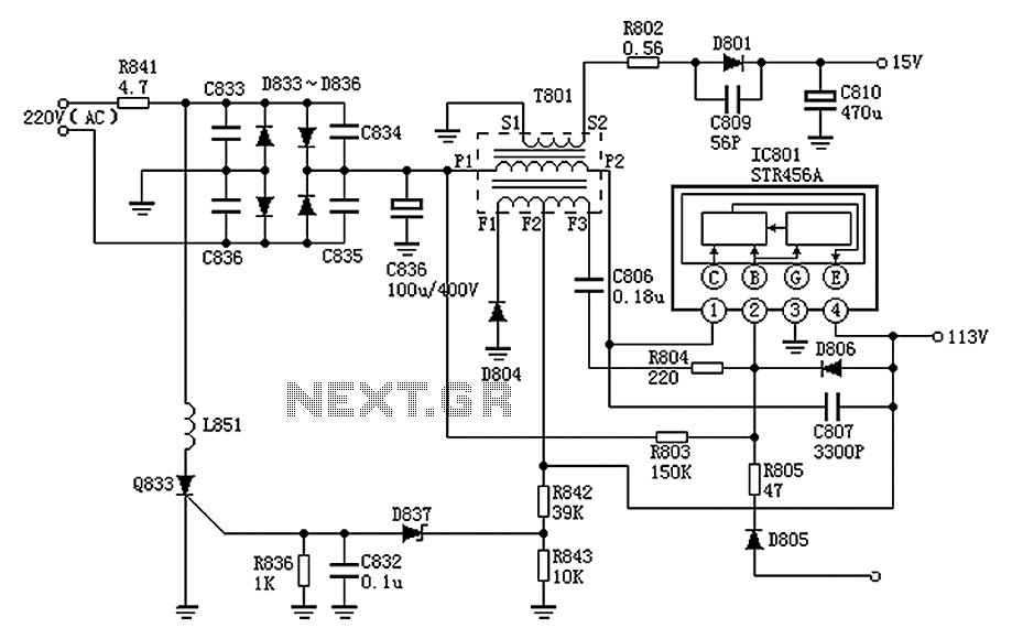
The Panasonic M12H switching power supply circuit is utilized in Panasonic models such as TC-230H, TC-2030DHN, TC-830D, and TC-840D. The circuit operates with an oscillation frequency that generates approximately 300V DC voltage at C836. The T801 transformer is involved...
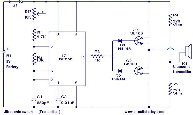
The transmitter part of the circuit is built around IC1 (NE 555), which is configured as an astable multivibrator operating at 40 kHz. The output from IC1 is amplified by a complementary pair of transistors (Q1 and Q2) and...