
Ultrasonic Sensor Switch
The ultrasonic motion detector circuit operates by transmitting an ultrasonic signal at a frequency of 40 kHz. This signal is emitted by a piezoelectric transducer, which converts electrical energy into ultrasonic sound waves. The circuit includes a receiver that listens for echoes of the transmitted signal. When movement occurs within the detection range, the echoes are altered, allowing the circuit to detect motion. The sensitivity can be adjusted using a trimpot, enabling the user to fine-tune the detection capabilities based on environmental conditions.
The fire alarm circuit functions by utilizing a light-dependent resistor (LDR) to detect smoke particles in the air. When smoke is present, it scatters light, causing a change in resistance in the LDR. This change is detected by a comparator circuit, which triggers an alarm when the resistance falls below a certain threshold, indicating the presence of smoke. This circuit is particularly valuable during the summer months when fire hazards increase due to dry conditions.
The switching voltage regulator circuit employs the LM317HV, a versatile adjustable voltage regulator, which can output a range of voltages from 1.8V to 32V. This is achieved by configuring external resistors that set the output voltage according to the desired application. The inclusion of the 2N3792 power PNP transistor allows the circuit to handle higher current loads, up to 3A, making it suitable for powering various electronic devices.
The long-range infrared transmitter circuit is designed to extend the operational range of standard infrared remote controls. By utilizing a more powerful IR LED and optimizing the circuit design, the range can be increased to 10 meters or more. This requires careful consideration of factors such as the power supply, modulation techniques, and the design of the IR receiver.
The FM wireless microphone circuit is designed to operate within the FM broadcast band, specifically tuned to 90 MHz. The circuit includes a variable tuned circuit that allows the user to select a frequency that minimizes interference from other broadcasts. This is crucial for achieving clear audio transmission. The PCB layout for this circuit is designed to minimize noise and ensure stable operation, making it suitable for various applications in audio transmission.This is a ultrasonic motion detector (or movement detector) circuit. The circuit claimed has a high movement sensitivity. Even air moving (hot air rising, wind blowing) will trigger it when the trimpot is set near the most sensitive position. The transmitter sends out a steady ultrasonic tone at 40kHz. At this frequency the wavelength is. This is the fire alarm circuit which use LDR to sense the smoke from the fire, so it can be used to detect any dark smoke. With the onset of summer season, possibilities of fire accidents go up. These fire accidents could be prevented if timely alarms are available. The circuit given right here alerts. Above circuit diagram is a easy, simple and cheap switching voltage regulator which has capability to deliver adjustable voltage output range of 1.
8V to 32V and static electric current of 3A. This regulator use adjustable regulator IC of LM317HV and a power PNP transistor of 2N3792. The LM317HV is adjustable 3-terminal positive voltage regulators capable. Here the long range/distance Infrared transmitter circuit, give you extra power for your Infrared transmitter. The majority of the IR remotes do the job reliably within a range of 5 metres. The circuit complexity increases in case you design the IR transmitter for good operation more than a extended distance, for example, 10 metres.
To. Below is the circuit diagram and PCB layout of FM wireless microphone: The range of frequencies for the FM broadcast band is 90MHz (MHz = Megahertz or 90 million cycles per second). Because the FM microphone has a variable tuned circuit, it can be tuned to a quiet spot on your local FM broadcast band.
🔗 External reference
Related Circuits
This DIY magnetic field sensor circuit is straightforward and capable of detecting both static magnetic fields and those that vary at audio frequencies. The unit is designed to be user-friendly and efficient. The magnetic field sensor circuit typically employs a...
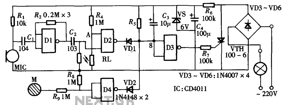
The circuit integrates sound and light control with touch functionality, creating a fully operational delay section light switch circuit. It consists of light control, voice circuits, and a touch control circuit, all triggered by a thyristor switch. The described circuit...
The integrated circuit input side contains an oscillating circuit, where the oscillation frequency is determined by the external components L1, C1, and the sensor's equivalent capacitance. The equivalent capacitance increases as the sensor is immersed in liquid. The oscillating...

This is a small circuit designed for use as a charging controller or voltage limiter. It is particularly useful for creating a solar charger. The assembly of the circuit allows for modifications according to personal preferences. The circuit is...

Similar to the CMOS-based touch switch available on this site, this transistor-based touch switch can activate a load simply by the user touching a metal plate. It is designed to directly switch a relay, allowing it to be used...
A simple circuit with which we have the possibility of opening and closing the RL1 contacts. It becomes active by touching a small metal surface. The status of RL1 is indicated by the LED D3. The supply voltage for...
Warning: include(partials/cookie-banner.php): Failed to open stream: Permission denied in /var/www/html/nextgr/view-circuit.php on line 713
Warning: include(): Failed opening 'partials/cookie-banner.php' for inclusion (include_path='.:/usr/share/php') in /var/www/html/nextgr/view-circuit.php on line 713