
simple touch switch circuit
This transistor-based touch switch circuit is an innovative solution for activating electrical loads without the need for traditional mechanical switches, which can be prone to failure in harsh conditions. The core of the circuit consists of a few transistors configured to detect the capacitance change when a user touches the metal plate, which serves as the touch sensor. The activation of the transistor allows current to flow to the relay coil, engaging the relay contacts to power the connected load.
The circuit can be powered by a standard 12V DC supply, making it compatible with various applications. The use of a latching relay is particularly advantageous, as it maintains the state of the load (on or off) even after the user removes their finger from the touch pad. This feature is beneficial for applications where continuous operation is desired without the need for constant user interaction.
To implement the touch pads, PCB material can be utilized for a more durable and reliable touch surface. The pads can be connected to the base of the transistors through a resistor, which helps to limit the current and protect the components from potential damage. The design allows for easy integration into existing systems, making it a versatile solution for various electronic projects.
For the second circuit that interrupts power to the latching relay, a standard relay can be employed. This relay will be activated by the second touch pad, which, when pressed, opens the normally closed contacts connected to the power supply of the latching relay, effectively turning off the load. This arrangement allows for a simple and intuitive user interface, where one touch pad activates the load and the other deactivates it.
Overall, this touch switch design is suitable for applications requiring reliable switching capabilities in environments where traditional switches may fail, offering a robust and user-friendly solution for controlling electrical loads.Similar to the CMOS based Touch Switch also on this site, this transistor based touch switch can activate a load simply by the user touching a metal plate. It is designed to directly switch a relay to allow it to be used with large loads. As it uses only a few commonly available transistors and a 12V supply, it is ideal for hostile environments wh
ere mechanical switches would be damaged. Using a latching relay and two of these circuits, a simple two pad "touch on/touch off" arrangement can be made. The touch pad can be most easily made by cutting a small square of PCB material and then soldering on a single wire.
Alternatively, something like a penny glued to a plastic backing will do the job. As mentioned, a latching relay can be used so that a momentary touch activates the relay and it remains active. To turn off a latching relay, power must be interrupted. So a 2nd circuit with a normal relay can be used to cut power (use the NC contacts on the 2nd circuit).
Placed side by side, two touch pads form an "on" and an "off" pad. 🔗 External reference
Related Circuits
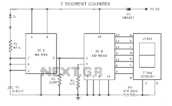
A display counter circuit is illustrated through a diagram featuring a seven-segment display controlled by the counter IC CD4033. This counter circuit is designed to visually represent incremental counts, enhancing its appeal for integration into various applications. An astable...
This circuit can manage nine independent telephones using a single telephone line pair located at nine different locations. It functions as a bidirectional telephone line simulator without the need for actual telephone lines, allowing for coupling, testing, and demonstration...
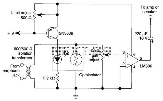
An optoisolator is utilized as an attenuator in this circuit. When the LM386 draws more current from audio signals, the 2N3638 activates, which biases the optoisolator on, thereby reducing the volume. The circuit employs an optoisolator to achieve signal attenuation,...

A simple remote control tester circuit with a diagram and schematic using the infrared sensor IC TSOP1738. An LED will blink when infrared waves fall on it, indicating the remote control is functioning. The remote control tester circuit utilizes the...
This circuit is designed to drive an ultrasonic transducer. A question has arisen regarding how to limit the output current, as a 60W transducer may be at risk of damage due to excessive current. Guidance or examples for integrating...
Pictures and a sample schematic (including pinouts) of an AMP hexadecimal (16-position) switch with a screw slot actuator. The AMP hexadecimal switch is a 16-position rotary switch designed for applications requiring multiple selectable options. This switch features a screw slot...
Warning: include(partials/cookie-banner.php): Failed to open stream: Permission denied in /var/www/html/nextgr/view-circuit.php on line 713
Warning: include(): Failed opening 'partials/cookie-banner.php' for inclusion (include_path='.:/usr/share/php') in /var/www/html/nextgr/view-circuit.php on line 713