
Battery status indicator circuit diagram
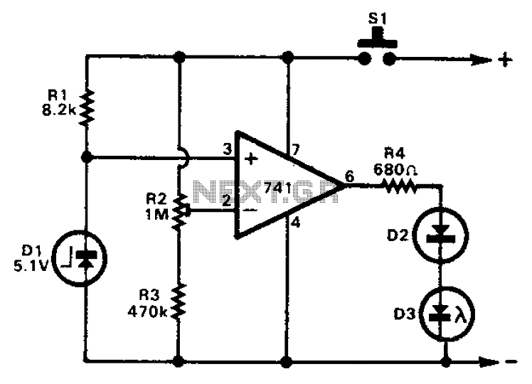
The 741 operational amplifier is a versatile component often utilized in various electronic applications, including voltage comparison. In this configuration, the op-amp operates in comparator mode, where the non-inverting input receives a voltage that is compared against a reference voltage derived from a Zener diode. The Zener diode is crucial for establishing a stable reference voltage of 5.1V, ensuring that the op-amp can accurately assess the input conditions.
Resistor R2 plays a significant role in this circuit by allowing for the adjustment of the in-phase input voltage. By setting R2 appropriately, the voltage at the non-inverting input can be scaled down to half of the total supply voltage. This scaling is essential for ensuring that the op-amp's output responds correctly to changes in the input voltage.
The operational amplifier's output will toggle based on the comparison between the non-inverting input voltage and the reference voltage. If the voltage at the non-inverting input exceeds 5.1V, the output of the op-amp will transition to a high state, potentially turning on a connected load, such as a light-emitting diode (LED). However, if the supply voltage is higher than 10.2V, the LED will not illuminate, indicating that the op-amp's output remains low despite the higher supply voltage. This behavior can be utilized in various applications where voltage thresholds need to be monitored and controlled, enhancing the circuit's functionality in automated systems.
In summary, the configuration of the 741 op-amp as a voltage comparator with a Zener reference voltage and adjustable input through R2 provides a reliable method for voltage monitoring and control within electronic circuits.741 op amp can be used as a voltage comparator. Non-inverting input and a zener control source. The reference voltage is 5.1V. R2 can adjust the in-phase input voltage becomes half the supply voltage. When the supply voltage is higher than 10.2V, the light emitting diode will not light up.
Related Circuits
Often, there is a need for an additional telephone ringer in an adjacent room to indicate an incoming call. For instance, if the telephone is located in the drawing room, an extra ringer may be required in the bedroom....
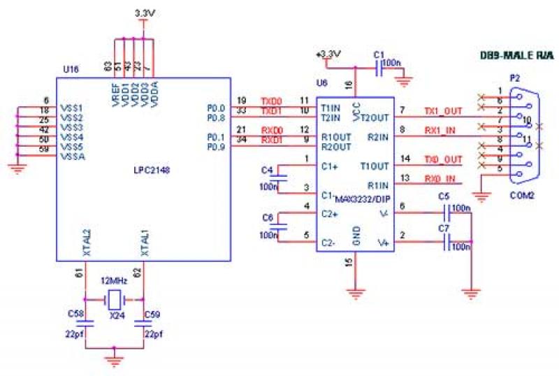
The interfacing of a Bluetooth module with the LPC2148 microcontroller is a straightforward process that enables the transmission of messages from the LPC2148 Primer Board to mobile devices via Bluetooth using UART0. Some delays may occur when sending a...
Most recent cars are equipped with a significant amount of electronics, including ABS brake systems, engine control with injection calculators, airbag activation, and various comfort functions. One such function, often overlooked due to its commonality, is the automatic activation...
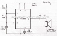
This circuit generates an oscillating frequency of approximately 1 kHz, which can be adjusted by changing the value of resistor R1. The speaker will emit a continuous beep sound at this frequency. The circuit utilizes a basic oscillator configuration,...
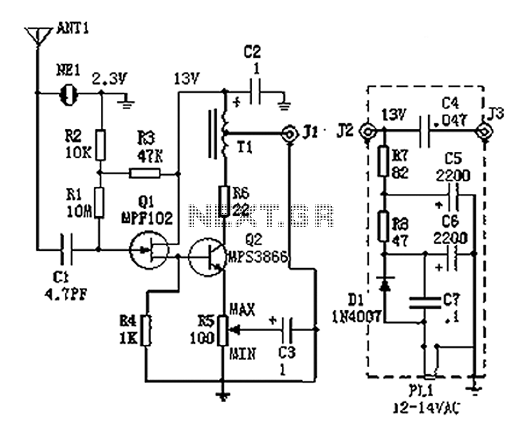
An active antenna operating within the frequency range of 100 kHz to 30 MHz, characterized by its compact size and effective performance. It is designed to be simple and low-cost, making it ideal for remote medium wave and short-wave...
The circuit comprises a 3-stage resistor-capacitor coupled amplifier. When ring button S2 is pressed, the amplifier circuit formed around transistors T1 and T2 gets converted into an asymmetrical astable multivibrator generating ring signals. These ring signals are amplified by...