
On After Delay with Mosfet

The On After Delay Circuit is designed to activate an output after a predetermined delay following the closure of switch S1. The use of a MOSFET provides advantages such as higher efficiency and faster switching capabilities compared to traditional transistors.
The circuit typically consists of a MOSFET, a resistor, a capacitor, and a switch. When S1 is pressed, current flows through the resistor, charging the capacitor. The time it takes for the capacitor to charge to a specific voltage level determines the delay period. Once the voltage across the capacitor reaches the threshold voltage of the MOSFET, the MOSFET turns on, allowing current to flow to the load.
The resistor-capacitor (RC) time constant is critical in determining the delay duration. The time constant (τ) can be calculated using the formula τ = R × C, where R is the resistance in ohms and C is the capacitance in farads. By selecting appropriate values for R and C, the desired delay can be achieved.
It is essential to ensure that the MOSFET selected can handle the load current and voltage requirements. Additionally, proper heat dissipation measures should be considered to prevent overheating during operation. The circuit can be used in various applications, such as timed lighting, motor control, or any scenario where a delayed activation is required.
Overall, the On After Delay Circuit is a versatile and efficient solution for implementing time delays in electronic systems.That be On After Delay Circuit. I uses mosfet in the circuit for delay easy more than the transistor. By have the work of the circuit be when press , S1 ,.. 🔗 External reference
Related Circuits
The Metal-Oxide-Semiconductor Field-Effect Transistor (MOSFET) is analogous to the Junction Field-Effect Transistor (JFET) in several aspects. Both types are voltage-driven unipolar devices that rely on either electron or hole movement, but not both, unlike bipolar transistors. A key structural...
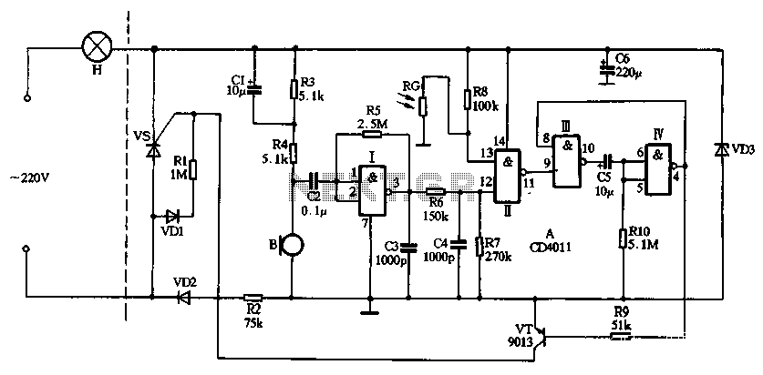
The circuit utilizes CD4011 digital circuits to create a sound-activated light lamp with a dual-control delay section. The left portion of the circuit represents the lighting lines, while the right part consists of the sound and light control delay...
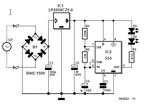
This article is relevant only to readers whose bicycle lights are powered by a dynamo. The regulations regarding bicycle lights in the United Kingdom are stricter than those in other regions. Dynamo-powered bicycle lights utilize a generator that converts mechanical...
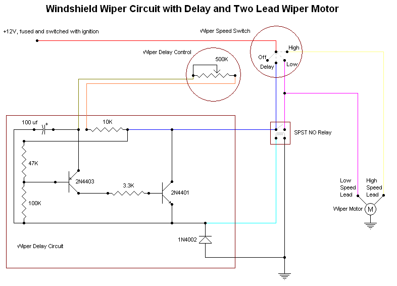
In some cases, a different wiper motor may be necessary, and rebuilt units are generally available at parts stores for a reasonable price. Once the required parts and manuals are obtained, installation of the appropriate switch, motor, and, if...
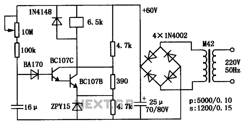
The circuit consists of a transistor relay delay pull mechanism. Initially, with a 16 µF capacitor at zero voltage, both transistors are off, and the relay remains inactive. As the 16 µF capacitor charges over time, the voltage increases...
Most cars do not have delayed interior lights. The circuit presented can rectify this issue by gradually switching the interior lights of a car on and off. This feature facilitates tasks such as locating the ignition keyhole after the...