
Dimmer With A MOSFET

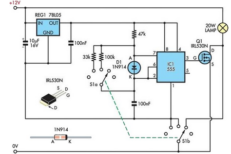
The described circuit employs a MOSFET as the primary switching element for dimming applications at mains voltage. The BUZ41A is a N-channel MOSFET capable of handling a maximum voltage of 500 V and a continuous drain current of 4.5 A, making it suitable for typical residential lighting applications. The use of a diode bridge allows for the conversion of AC voltage to a pulsed DC voltage, which the MOSFET can effectively control.
In operation, the MOSFET is driven by a control signal that modulates its gate voltage, allowing for the adjustment of the power delivered to the load. When the gate voltage exceeds the MOSFET's threshold voltage, the device turns on, allowing current to flow through the load. By varying the duration of the gate signal, the average power supplied to the load can be controlled, achieving the desired dimming effect.
This configuration eliminates the need for a triac, which is traditionally used in dimmer circuits, thereby simplifying the design and potentially enhancing reliability. The MOSFET's faster switching capabilities can lead to improved efficiency and reduced heat generation compared to triac-based designs.
Additional components may include resistors for gate biasing, capacitors for filtering, and protection diodes to safeguard the MOSFET from voltage spikes. Proper thermal management is also essential to ensure the MOSFET operates within its safe limits, as excessive heat can lead to failure.
Overall, this circuit exemplifies a modern approach to dimming solutions, leveraging the advantages of MOSFET technology while providing a robust alternative to traditional triac-based dimmers.This circuit shows that dimmers intended for use at mains voltage do not always have to contain a triac. Here, a MOSFET (BUZ41A, 500 V/4.5A) in a diode br.. 🔗 External reference
Related Circuits
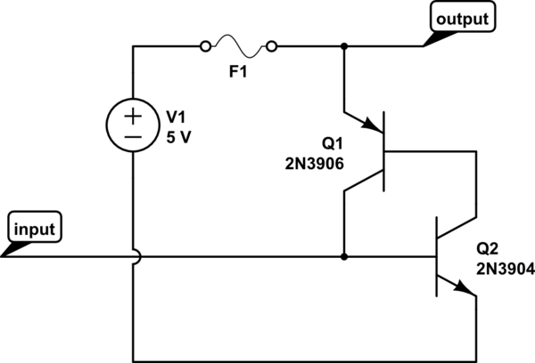
The circuit should default to the "on" state when first connected. However, if a specific signal goes high for a brief duration (approximately 10 microseconds), the circuit should turn off and remain off. The challenge lies in achieving the...
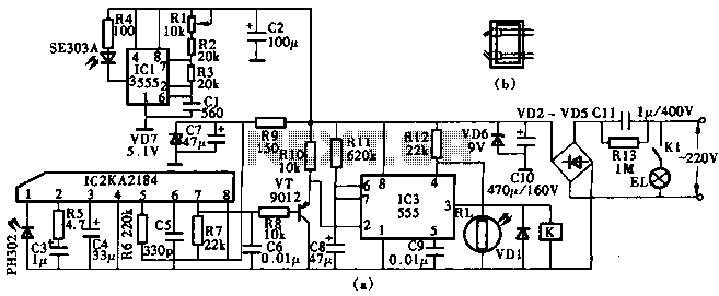
This circuit utilizes the KA2184 infrared receiver ASIC for an infrared remote control dimmer light application, as depicted in the schematic. The infrared signal is generated by a pulse generator using an NE555 timer integrated circuit. The NE555 produces...
This MOSFET FM transmitter circuit is designed for aligning FM radio receivers. It features a microphone amplifier with automatic gain control. The FM modulation is achieved using a voltage oscillator, and the final stage employs MOSFETs. A low-pass filter...
A 12V 20W halogen lamp (MR16) and a 4.2Ah SLA battery are utilized in a bike light system. Due to the limited lifespan of the battery at this power rating, a cost-effective light dimmer was designed to reduce battery...
This circuit is designed to dim lights with a maximum capacity of approximately 350 watts. It employs a standard TRIAC circuit configuration, which has been observed to generate minimal heat during operation. It is important to note that this...
This amplifier is designed to be as flexible as possible, with no bad habits. Indeed, it will operate stably with supply voltages as low as +/-5V (completely pointless, but interesting), all the way to the maximum supply voltage of...