
Mosfet Tester
The astable multivibrator circuit is a type of oscillator that continuously switches between its high and low states without requiring any external triggering. This makes it particularly useful for applications like testing MOSFETs, where a square wave signal is needed to effectively drive the gate of the device under test.
The circuit typically consists of two resistors (R1 and R2) and a capacitor (C1) connected to an N-channel MOSFET. The resistors are used to set the charging and discharging times of the capacitor, which in turn determines the frequency of the oscillation. The output can be taken from the drain of the MOSFET, which will produce a square wave signal.
When testing an N-channel MOSFET such as the IRF830, the gate of the MOSFET is connected to the output of the astable multivibrator. The square wave signal will turn the MOSFET on and off rapidly. By observing the output at the drain, one can assess whether the MOSFET is functioning properly. If the MOSFET turns on and off in response to the square wave signal, it indicates that the device is operational.
The values of the resistors and capacitor can be adjusted to change the frequency of the output signal, allowing for testing across different operational conditions. Proper selection of these components is crucial for ensuring that the MOSFET is driven adequately within its specified gate threshold voltage range.
This astable multivibrator circuit serves as a simple yet effective means for evaluating the performance of power MOSFETs, providing a visual indication of their operational status through the generated square wave output.This circuit included in the category astable multivibrator. This circuit is used to test? N-Mosfets (the power kind e.g irf830), whether it works or not. If. 🔗 External reference
Related Circuits
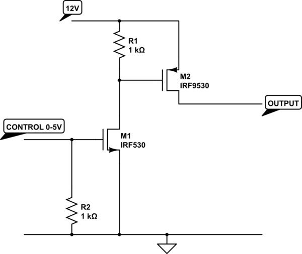
The transistor depicted is a P-channel MOSFET functioning as a high-side switch. Typically, an N-channel MOSFET is preferred for low-side switching, but the P-channel variant can be utilized effectively with the addition of a load at the drain. When...
A circuit for an offline telephone tester that does not require a telephone line for testing a telephone instrument. The circuit is simple enough to be assembled by a novice with minimal electronics knowledge. A telephone line can be...
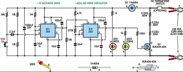
This circuit is designed to assess the condition of lead-acid and gel cell batteries with capacities exceeding 20Ah. It switches a load of approximately 18A at a frequency close to 50Hz, allowing for the measurement of the battery's internal...
Firstly, we will describe the add-on version for the 5x7 Display as this is the cheapest version and, quite frankly, it only deserves a few dollars as a piece of test equipment. It's all the rage to have an...
I designed a simple sinewave generator based on a Analog Devices AD9832 chip. It will generate a sinewave from 0.005 to 12 MHz in 0.005 Hz steps. That's pretty good, and definitely good enough for me! But while waiting...
This circuit utilizes the widely available LM3914 integrated circuit (IC), which is straightforward to operate and does not require external voltage regulators due to its built-in voltage regulator. It can be powered from various sources. When the test button...