
motion motor control servo system block

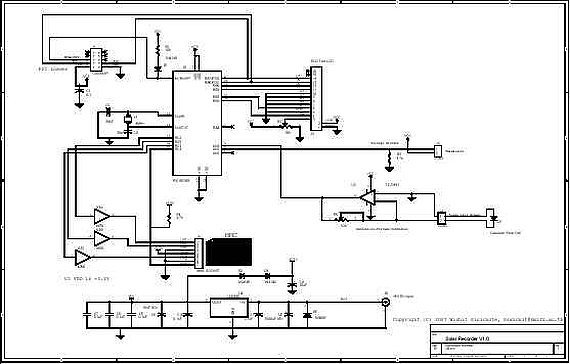
The block diagram presented illustrates the architecture of a modern automated motion control system, emphasizing the integration of closed-loop feedback mechanisms. At its core, the servo system consists of critical components such as feedback sensors, motor drivers, and control circuitry, which collectively ensure precise regulation of motor speed and positioning.
The feedback elements, typically comprising encoders, provide real-time data regarding the motor's position and speed. This information is relayed to the motion controller, which processes the signals using a motion-control IC, microprocessor, or DSP. These processing units are essential for interpreting the encoder signals and for generating the necessary control outputs to the motor driver.
The motor driver, which may consist of an amplifier, receives commands from the motion controller. It is responsible for delivering the correct voltage and current levels to the motor, thereby facilitating accurate motion execution. The integration of these components allows for dynamic adjustments based on feedback, ensuring that the system can maintain stability and precision even under varying operational conditions.
In designing a fault-tolerant motion-control system, several critical factors must be addressed. The layout of the receiver circuit's PC board must be optimized to minimize noise and interference, which can adversely affect performance. Moreover, the cabling system for encoder signals should be robust and shielded to prevent signal degradation.
It is also important to incorporate safety features such as hard-wired emergency stop and limit inputs into the motion controller. These features enhance the reliability of the system by providing immediate shutdown capabilities in case of faults or emergencies. Overall, a well-designed motion-control system integrates these elements cohesively, ensuring operational reliability and safety while achieving the desired motion performance.This is a figure for a block diagram of a modern automated systems incorporate closed-loop feedback for motion control. They typically include a servo system that consist of feedback elements and motor driver combined in a manner.
This will give accurate and stable control over speed and position. Below is the illustration of the various system-le vel components of a typical servo system. This is the figure of the diagram; For processing the high-speed encoder signals, typical motion-controller cards and modules include a motion-control IC, a microprocessor, and a DSP or custom ASIC. Velocity and direction of rotation signals to the driver or amplifier is provided by the controller which in turn provides the proper levels of voltage and current (power) to operate the motor.
We must have address the following items at the system level to design robust and fault-tolerant motion-control system with feedback during design: Controller-encoder input circuits (receiver circuits), Receiver circuit PC-board layout and Encoder-signal cabling system. Motion-controller inputs, such as hard-wired emergency stop and limit inputs, should also be considered when designing a fault-tolerant feedback system though not addressed in this article.
🔗 External reference
Related Circuits
A device for measuring daily insolation has been developed. The device is constructed using a PIC18F458 microcontroller and a 128MB Multimedia Memory Card (MMC). The insolation measurement device leverages the capabilities of the PIC18F458 microcontroller, which is known for...
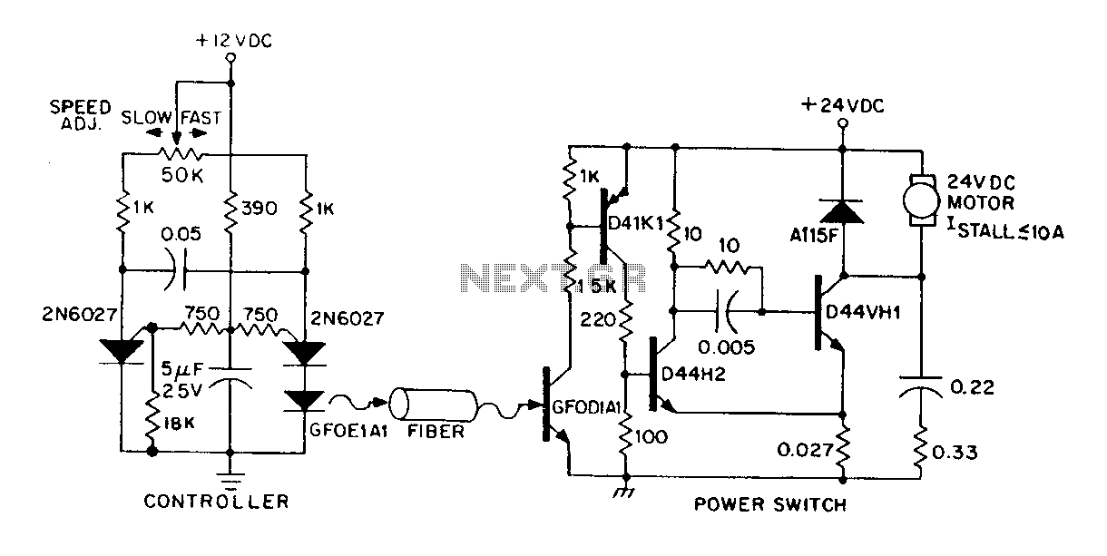
A DC power supply can be controlled through an optical fiber. The circuit includes a small DC motor (1/12 hp) that offers an isolated speed control channel. The control logic operates as an independent module, consuming 300 mW of...
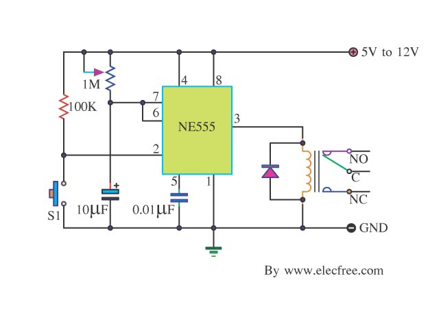
Many friends take an interest in the circuit involving the highly popular IC 555, which is an integrated circuit. This circuit sets the time in a basic manner. The IC 555 timer is a versatile and widely utilized component in...
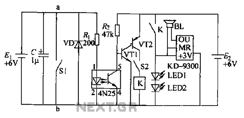
Due to the fast pace of modern life, intense competition, and widespread insomnia, which poses health risks, this section presents a feasible and effective method for controlling photoelectric hypnotic music to alleviate insomnia and facilitate sleep. The principle circuit...

R1 is a 15k ohm resistor. An NTC thermistor rated at 10k ohm, available at Radio Shack in the United States, is utilized. P1 is a 10k ohm potentiometer that sets the low speed (voltage) of the fans at...
A DC motor from an old personal stereo cassette player has been utilized in this circuit, which provides control over both the speed and direction of the motor. The circuit employs PWM waveforms to drive a MOSFET H-bridge, as...