
Wiper Speed Control

The circuit operates by utilizing the NE555 timer ICs in two different configurations to achieve a flexible wiper control system. The first NE555 timer (IC1) functions as a monostable multivibrator, generating a single output pulse upon the momentary activation of switch S1. This pulse serves as a clock signal for the CD4017 decade counter (IC2), which counts the pulses and allows the user to select different timing intervals for the wiper's operation. The decade counter outputs are connected to variable resistors (VR1 to VR10), which are preset to different resistance values through empirical adjustments.
The selected output from IC2 is used to determine which variable resistor is active in conjunction with resistors R4 and R5, which are part of the timing circuit for the second NE555 timer (IC3) configured in astable mode. The astable configuration allows for continuous oscillation, generating a square wave output whose frequency can be adjusted by changing the resistance values of the selected variable resistor.
The output from IC3 is responsible for driving the TIP32 transistor (T1), which acts as a switch to control the larger power transistor (T2, 2N3055). This configuration allows the circuit to manage the higher current required by the wiper motor, enabling it to function at the chosen speed based on the settings determined by the user. The entire circuit is powered by the vehicle’s battery, ensuring that it operates reliably under automotive conditions. The design effectively addresses the issue of a continuously running wiper by providing adjustable timing intervals, enhancing the user's driving experience during varying weather conditions.A continuously working wiper in a car may prove to be a nuisance, especially when it is not raining heavily. By using the circuit described here one can vary sweeping rate of the wiper from once a second to once in ten seconds The circuit comprises two timer NE555 ICs, one CD4017 decade counter, one TIP32 driver transistor, a 2N3055 power transist
or (or TIP3055) and a few other discrete components. Timer IC1 is configured as a mono- stable multivibrator which produces a pulse when one presses switch S1 momentarily. This pulse acts as a clock pulse for the decade counter (IC2) which advances by one count on each successive clock pulse or the push of switch S1.
Ten presets (VR1 through VR10), set for different values by trial and error, are used at the ten outputs of IC2. But since only one output of IC2 is high at a time, only one preset (at selected output) effectively comes in series with timing resistors R4 and R5 connected in the circuit of timer IC3 which functions in astable mode.
As presets VR1 through VR10 are set for different values, different time periods (or frequencies) for astable multivibrator IC3 can be selected. The output of IC3 is applied to pnp driver transistor T1 (TIP32) for driving the final power transistor T2 (2N3055) which in turn drives the wiper motor at the selected sweep speed.
The power supply for the wiper motor as well as the circuit is tapped from the vehicle`s battery itself. The duration of monostable multivibrator IC1 is set for a nearly one second period. 🔗 External reference
Related Circuits
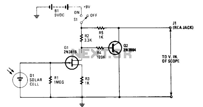
The solar cell is connected to the input of the field-effect transistor (FET), Q1, allowing it to generate a positive DC voltage at the gate when illuminated by light through the open shutter. This illumination reduces the negative gate-source...
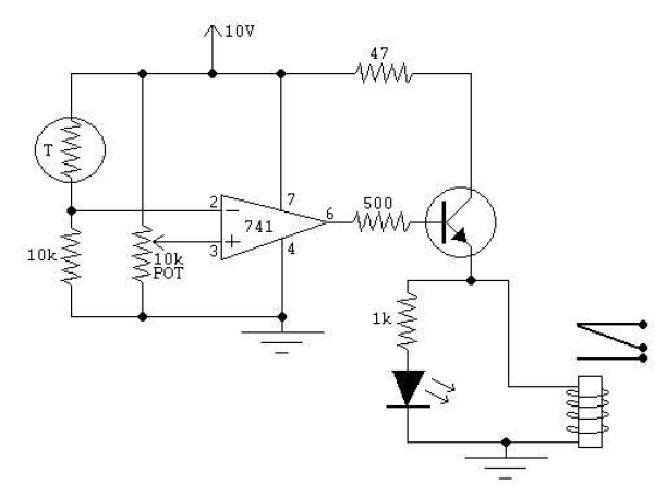
There is no prior experience in building controllers, and there is uncertainty about how to begin. A budget constraint of less than 100 euros is present. A power thyristor is already available. The inquiry revolves around the best method...
The Arduino microcontroller board can supply a current of 40mA from its output connections, with digital outputs fixed at 5V for "ON" and 0V for "OFF." This current is suitable for LEDs, but devices like motors, solenoids, and high-brightness...
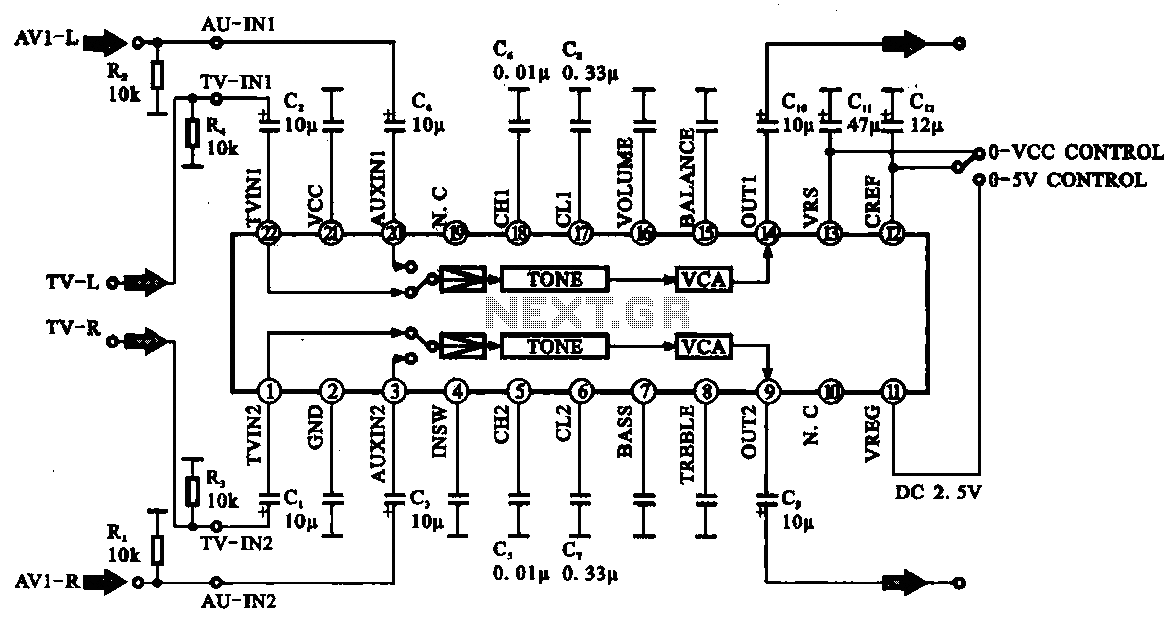
Audio signal control circuit. It illustrates a typical audio signal control circuit where two audio signals enter the integrated circuit through switching and tone controls (treble and bass), subsequently adjusting the output sent to the audio power amplifier. The audio...
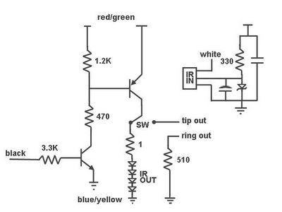
This system is designed to distribute infrared (IR) commands throughout a residence. It is particularly beneficial for controlling audio/visual (A/V) equipment located in one room from multiple other rooms. The project utilizes a Microchip PIC 16F877 microcontroller to manage...
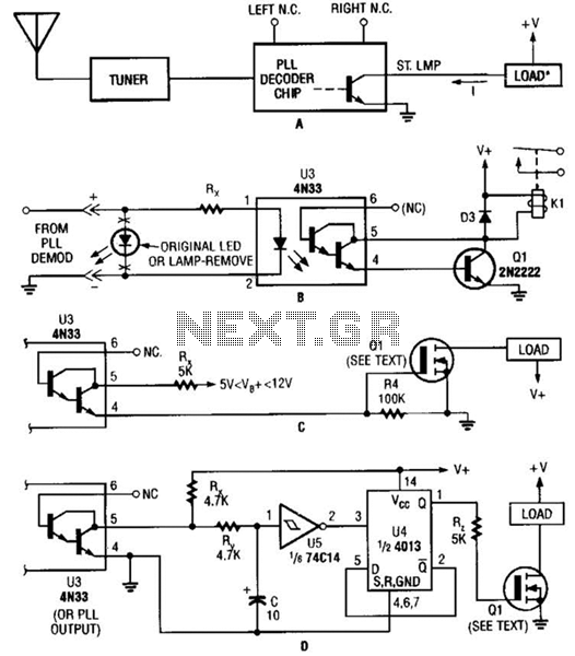
Several possible interface circuits are presented for use with a remote-control transmitter. The circuit labeled A demonstrates a typical FM stereo MUX decoder with a load connected directly to the open-collector output of a TA7343 PLL. The circuit labeled...