
Frequency sensitive rheostat for manual and automatic way starting circuit

The circuit operates by utilizing a relay (KA) that has a normally closed contact configuration. In the manual mode, the user can initiate the heating element directly, while in the automatic mode, the circuit is designed to manage the heating element's operation based on predefined conditions.
At startup, the relay KA's normally closed contact ensures that the heating element is engaged immediately. This design choice is critical as it minimizes the startup time, which is essential for preventing the thermal relay from overheating or malfunctioning. The thermal relay is responsible for monitoring the temperature of the heating element and protecting the system from overheating. If the startup time is excessive, the thermal relay may trip, leading to a failure in the boot process.
In the circuit, various components work together to ensure safe and efficient operation. The relay KA is activated by a control signal that determines whether the circuit is in manual or automatic mode. Additional components may include fuses for overcurrent protection, temperature sensors for real-time monitoring, and control logic to switch between manual and automatic operations.
Overall, the design emphasizes reliability and efficiency, ensuring that the heating element operates within safe temperature limits while providing flexibility for user control. Proper implementation of this circuit can enhance the performance of heating applications, making it suitable for various industrial and commercial uses. Circuit shown in Figure 3-164. The circuit can be manual and automatic two ways. During startup, KA normally closed contact relay FR hot heating element shorted, in order to av oid start-up time is longer cause thermal relay malfunction affect the boot.
Related Circuits

This is a design for a flashlight that two 220 V alternating lights can control. The flashlight uses only one IC. IC1a IC1c to be used for the flashing signal generation. The output of IC1c thyristor T1 is controlled,...
Comprehensive information regarding the RF Field Strength Meter Circuit is available. Users can learn about and download the RF Field Strength Meter Circuit online. The RF Field Strength Meter Circuit is designed to measure the strength of radio frequency (RF)...
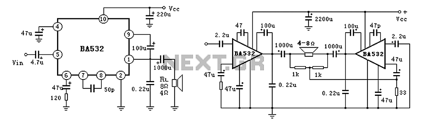
BA532 is a low-frequency power amplifier circuit designed for an output transformerless (OTL) application, capable of delivering up to 5.8W of output power. It features built-in protection against load short-circuits, over-voltage, and over-temperature conditions. The amplifier is housed in...

Engineer Radu Preda from Romania has developed two energy-saving lighting circuits designed to control the duration that lights are activated, ultimately aiming to reduce electricity expenses. The first circuit utilizes a relay, while the second employs an optoisolator triac...

The LR inputs are summed, processed, and then drive a comparator. This comparator detects levels and generates transitions when audio inputs exceed or fall below predetermined thresholds. The frequency of these transitions, which correspond to rapid volume changes, is...
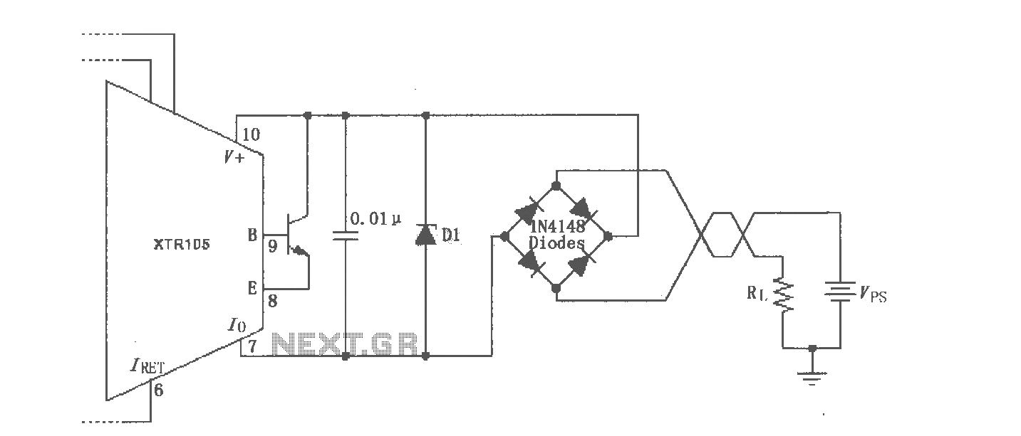
The XTR105 reverse voltage and over-voltage surge protection circuit is illustrated. A Zener diode rated at 36V can be utilized, with options including 1N4753A or 1N6286A. The maximum supply voltage (Vps) should be less than the minimum breakdown voltage...