
Permanent Magnet Motor Control with SCR
The Permanent Magnet Motor Control circuit is designed to efficiently manage the performance of permanent magnet motors, which are widely used in various applications due to their high efficiency and compact size. The schematic typically includes key components such as a microcontroller, power transistors, and feedback mechanisms to regulate motor speed and torque.
At the core of the circuit is the microcontroller, which processes input signals from sensors or user interfaces to determine the desired motor performance. The microcontroller sends control signals to power transistors or MOSFETs, which act as electronic switches to regulate the voltage and current supplied to the motor. This allows for precise control over the motor's speed and direction.
Feedback mechanisms, such as encoders or Hall effect sensors, are often integrated into the circuit to monitor the motor's actual speed and position. This data is fed back to the microcontroller, enabling closed-loop control that adjusts the input signals based on real-time performance, ensuring optimal operation and preventing issues such as stalling or overheating.
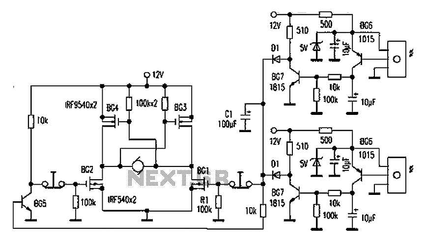
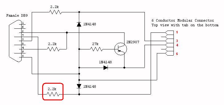
Additional components may include capacitors for filtering, diodes for protection against back EMF, and resistors for current limiting. The layout of the circuit is crucial for minimizing electromagnetic interference and ensuring stable operation. Proper grounding and component placement are essential to enhance the overall reliability and performance of the Permanent Magnet Motor Control circuit.This is a schematic diagram of Permanent Magnet Motor Control circuit. This circuit is used to control the permanent magnet control. This circuit uses. 🔗 External reference
Related Circuits
Automatic door control systems typically have a high market price for finished products. The proposed method is suitable for home use, utilizing easily accessible components. This design is ideal for those interested in creating their own automatic door system....
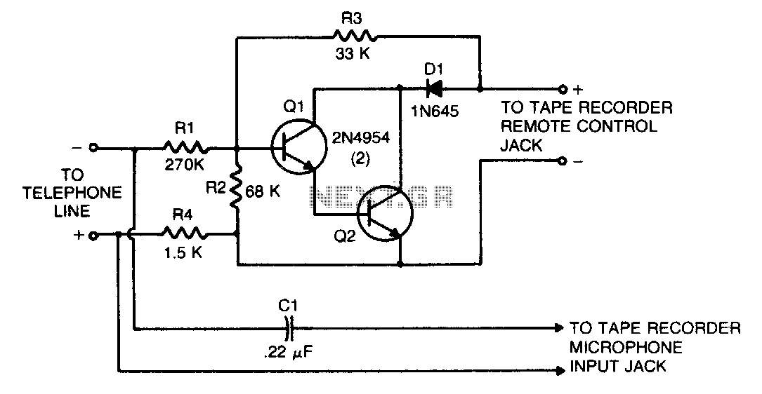
This circuit transforms a tape recorder into a fully automatic device for recording telephone conversations without requiring an external power source. The voltage at the switch terminals of the tape recorder is applied to a pair of Darlington-connected transistors,...
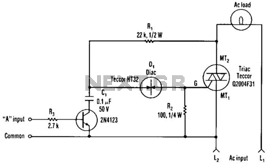
The single transistor connected between the capacitor and the common side of the AC line allows a logic-level signal to control this TRIAC power circuit. Resistor R2 prevents false triggering of the TRIAC by the trickle current through the...
This article provides an overview of the R100 and MCR100 UHF repeaters. All information was obtained from a physical examination of the station, the programming software, and the R100 Instruction (and service) Manual, p/n 6881078E15, as well as the...
The figure illustrates a simplified representation of the Earth's dipole magnetic field, resembling that of a bar magnet. Field lines originate from the south magnetic pole and terminate at the north magnetic pole. The angle at which this field...
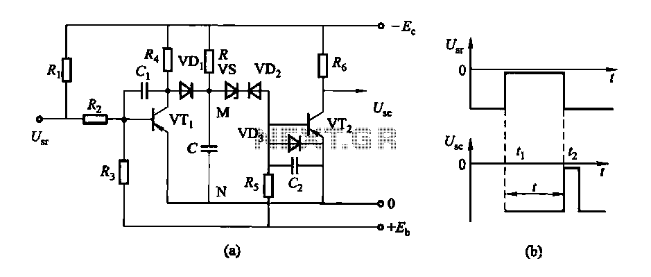
The circuit features a delay action with an instantaneous reset control mechanism. It is categorized into three types: a conducting pipe rechargeable delay circuit, a tube cut-off control rechargeable delay circuit, and a discharge-type delay circuit. In the conducting...