
motor switch led circuit
The circuit design described involves a methodical approach to building and testing an Arduino-based control system that integrates an LED and a switch with motor control capabilities. The process begins with the flashing of an LED, which serves as a basic confirmation of the Arduino's functionality. By following the outlined steps in the Arduino Guide, the LED's operation under computer control can be validated, ensuring that the microcontroller is correctly programmed and operational.
Next, the switch reading functionality is tested. The switch should be connected to a designated I/O pin, and the expected behavior is that the output changes from high (1) to low (0) when the switch is activated. Voltage measurements at the designated pin provide a quick diagnostic tool to confirm proper electrical behavior. The use of a DMM to check for continuity and voltage levels is critical in troubleshooting potential issues in the circuit, particularly with respect to the switch's operational integrity.
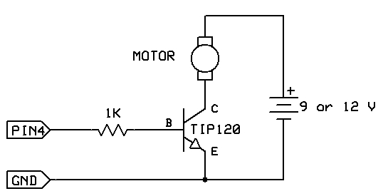
The motor control section of the circuit employs a TIP120 transistor, which acts as a switch to manage the higher current requirements of the motor without overloading the Arduino. This design choice is essential to prevent damage to the microcontroller. A separate power source, such as a 9V or 12V battery, is utilized to power the motor, ensuring that the Arduino remains within safe operating voltage levels. The transistor's emitter is connected to ground, and the collector is linked to the motor, allowing for effective control over the motor's operation through the Arduino.
For smaller motors, the 2N3904 transistor is suggested, which is suited for lower current applications. It is important to ensure that the connections are made correctly, particularly the polarity of the battery, to avoid damaging the Arduino. The jumper wire test provides a straightforward method to verify the motor's functionality, confirming that the circuit is correctly assembled and that the transistor is functioning as intended. Overall, this systematic approach to circuit assembly and testing facilitates the development of a reliable and functional electronic control system.The strategy is to get the circuit going in stages, testing each part as you go. Once everything is wired correctly and can be either controlled or read by the computer correctly, then you can write the main program with confidence that all the pieces are working. Follow the directions shown in the Arduino Guide ( PDF file ) under the "Flashing an LED" section. Use this program to confirm that the LED works under computer control Follow the directions shown in the Arduino Guide under "Reading a Switch". Use the program shown in the Guide to confirm that the Arduino is reading the switch properly. The stream of 1`s going across the monitor window should change to 0`s when you close the switch. If it doesn`t, read the voltage at Pin 3 with your DMM. It should be 5 V with the switch open and 0 V with the switch closed. If it isn`t, remove the switch from the circuit and check for continuity with the beeper function of your DMM.
The DMM should beep when the switch is closed (short circuit) and stay silent when open (open circuit). Sometimes switch contacts get dirty so if you aren`t getting a short circuit, try wiggling the switch button while it is closed.
The code assumes the switch is connected to Pin 3 on the Arduino, but any pin can be used. Do not connect your motor directly to an Arduino pin and do not use the 5 V power from the Arduino board to power your motor. Instead, control the motor using your TIP120 transistor and a separate 9V or 12V battery. The motor can be either the gear motor or the small motor. For the small motor, you can use the 2N3904 transistor as the switch. "Px" is any I/O pin on your Arduino. For this exercise, use P4. Connect the minus of the battery to the emmiter of the transistor (E pin) and then also connect the emmiter of the transistor to GND on the Arduino board.
Check these connections carefully because you never want the plus of the battery to directly connect to an Arduino pin. To check if things are working, take a jumper wire and short the collector to the emmiter pins of the transistor.
The motor should turn on. If not, check the wiring. 🔗 External reference
Related Circuits
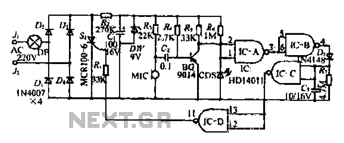
The circuit operates at 380V for air flow. Power is supplied through a step-down transformer, which rectifies the output to 9V DC. When the pump operates correctly, a button labeled 'S' is activated. The circuit utilizes a TWH8778 component....
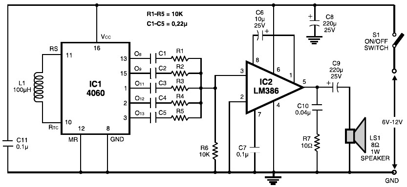
The circuit is built around the popular CMOS oscillator-divider IC 4060 and a small audio amplifier LM386. The IC 4060 functions as a multitone generator. A 100 H inductor is used at the input of the IC 4060, allowing...

Figure 555 illustrates a simple logic circuit test lead. The test pen utilizes the 555 timer IC as its core component, incorporating a Schmitt trigger to assess the logic state of digital circuits. The circuit has two outputs: when...

The circuit utilizes three 3PDT toggle switches, a momentary soft-touch SPST footswitch, and a 4DPT footswitch. While these components are not rare, they are less commonly available than standard pedal parts. The design may be somewhat compact for larger...

This design outlines a sensor circuit that utilizes an LED as a light sensor. The operational control and amplification of the output are managed by a 1458 integrated circuit (IC), which functions as an operational amplifier (op-amp). The circuit...
Schematic of an automatic solar garden light circuit with 10 super bright white LEDs that will automatically activate at night. The automatic solar garden light circuit is designed to harness solar energy for illumination purposes during nighttime. The circuit typically...
Warning: include(partials/cookie-banner.php): Failed to open stream: Permission denied in /var/www/html/nextgr/view-circuit.php on line 713
Warning: include(): Failed opening 'partials/cookie-banner.php' for inclusion (include_path='.:/usr/share/php') in /var/www/html/nextgr/view-circuit.php on line 713