
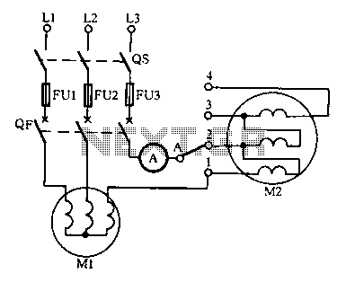
Motor winding circuit diagram of the current imbalance dried
The circuit for drying motor winding current imbalance is designed to address the issue of uneven current distribution across the windings of an electric motor. This imbalance can lead to overheating, reduced efficiency, and potential damage to the motor. The schematic typically includes components such as resistors, capacitors, diodes, and a microcontroller or relay for monitoring and control.
In the circuit, current sensors are strategically placed to measure the current flowing through each winding. These sensors provide real-time feedback to the control unit, which processes the data to determine if any windings are receiving an unequal amount of current. If an imbalance is detected, the control unit activates a drying sequence.
The drying process usually involves applying a controlled voltage to the affected winding(s) to facilitate the evaporation of moisture that may have accumulated due to environmental factors. This is often achieved through the use of resistive heating elements that can be integrated into the circuit. The resistors are chosen based on their power rating to ensure they can handle the necessary load without overheating.
Diodes may be included to protect the circuit from reverse voltage spikes, which can occur when the motor is switched off or during transient conditions. Additionally, capacitors can be used to smooth out voltage fluctuations and improve the overall stability of the circuit.
The final output of the circuit is a balanced current distribution across the motor windings, ensuring optimal performance and longevity of the motor. Proper design and implementation of this circuit are crucial for maintaining the reliability of electric motors in various applications.Drying the motor winding circuit current imbalance Below is a circuit diagram of the motor winding current imbalance drying:
Related Circuits
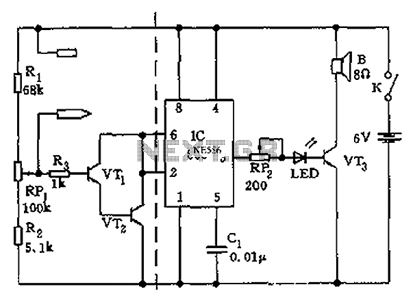
The apparatus consists of a cavers point detection circuit and a triggering display circuit. The cavers instrument functions as a test probe, which, when held in one hand, can detect acupuncture points by touching the skin with another probe....

This is a simple circuit that can be used as a sequential signal light in automobiles. The circuit is based on two integrated circuits (ICs): a TS 555 CN CMOS timer IC and a CD4017 decade counter IC. The...

The field scanning circuit generates sawtooth waveforms essential for color television field scanning. The circuit, as illustrated in Figure 1, is utilized in the Toshiba 2150 TV. The vertical scan pulse signal is produced from the LA7837 integrated circuit,...
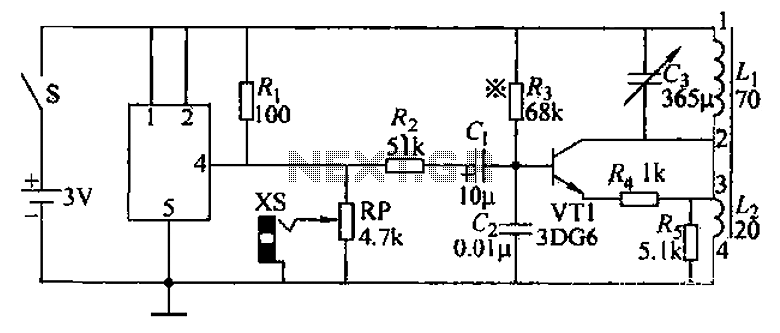
An audio frequency signal generator can output audio signals, 465 kHz spectral amplitude signals, and 52.5 Hz to 16 kHz high-frequency amplitude-modulated signals. The high-frequency oscillator's vibration frequency is determined by the components G and L. A variety of...

The following circuit is a simple, inexpensive, and easy-to-build motorcycle alarm. The circuit requires only two transistors to drive a relay, which acts as a switch to activate a buzzer. Any number of normally-open switches can be used. Mercury...
For the shorter wavelength VHF and UHF bands, it is more practical to construct complex antennas such as a single-band Slim Jim or Yagis. Various projects include creating an electronic unit, as it is necessary for the Intermediate Level...