
Ultrasonic drilling machine circuit diagram 2
The ultrasonic drilling machine operates by utilizing high-frequency sound waves to facilitate drilling processes. The power supply circuit provides the necessary voltage and current to the entire system, ensuring stable operation. This circuit typically includes voltage regulators and filtering components to maintain a consistent output.
The ultrasonic oscillator circuit is the heart of the system, generating the high-frequency signals required for ultrasonic drilling. It employs a combination of resistors (R1 to R4), which determine the frequency and amplitude of the oscillations, and a transistor (V1) that acts as a switch to control the flow of current. Capacitors (C1 to C4) are used for tuning and stability, while the inductor (L) helps in shaping the oscillation waveform.
Following the oscillator, the preamplifier circuit boosts the weak signals produced by the ultrasonic oscillator. This stage is critical for ensuring that the signals are strong enough for further amplification. The promoting amplifier circuit then takes these signals and amplifies them further, preparing them for the final power amplification stage.
The power amplifier output circuit is responsible for driving the ultrasonic transducer, which converts electrical signals into mechanical vibrations. This stage must be designed to handle high power levels while maintaining efficiency and stability. Overall, each component in the ultrasonic drilling machine circuit plays a vital role in ensuring the effective generation and application of ultrasonic energy for drilling applications.The ultrasonic drilling machine circuit is composed of power supply circuit, ultrasonic oscillator circuit, preamplifier, promoting amplifier circuit and power amplifier output circuit, and the circuit is shown as the chart. Ultrasonic oscillator circuit consists of resistors R1 ~ R4, transistor V1, capacitors C1 ~ C4 and inductor L.
Preamplifier circuit con.. 🔗 External reference
Related Circuits
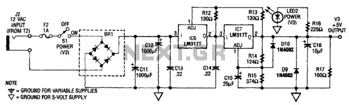
The power supply presented is intended to function with a wall transformer. This circuit can be utilized alongside a variable supply for testing circuits in a laboratory setting. T2 serves as a 12-V wall transformer. The power supply circuit is...
This single transistor audio mixer is utilized in an amplifier circuit design featuring a base-driven transistor, with its emitter being current-controlled. This audio mixer circuit employs a single transistor to facilitate the mixing of audio signals. The transistor operates in...
A series of emails have been received requesting schematics for infrared remotes. This document presents a schematic for such a remote, which transmits a tone using an infrared LED. The tone is decoded by the receiver, ensuring that the...
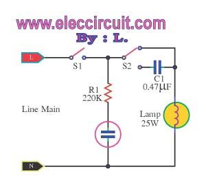
This is an automatic light dimmer circuit that eliminates the need for manual adjustment of light levels. It utilizes a Light Dependent Resistor (LDR) to detect ambient light conditions, which in turn controls a Triac to adjust the brightness...
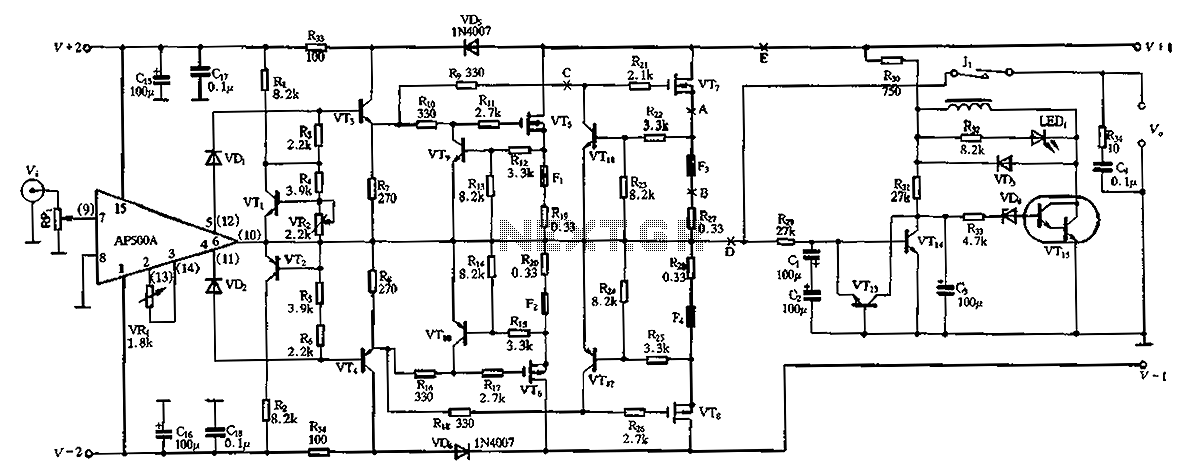
The CPI is a 100W DC super power amplifier circuit based on the AP500. It features a parallel push-pull amplifier output stage composed of transistors VT5, VT6, and VT7 to enhance output power. The circuit's output power is low...
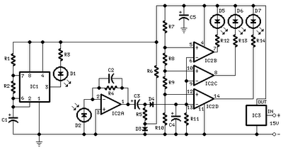
All distances mentioned can vary depending on the infrared transmitting and receiving LEDs used and are significantly affected by the color of the reflecting surface. Black surfaces greatly reduce the device's sensitivity. This circuit can also be applied in...
Warning: include(partials/cookie-banner.php): Failed to open stream: Permission denied in /var/www/html/nextgr/view-circuit.php on line 713
Warning: include(): Failed opening 'partials/cookie-banner.php' for inclusion (include_path='.:/usr/share/php') in /var/www/html/nextgr/view-circuit.php on line 713