
Multi-Melody Generator With Instrumental Effect

The melody generator circuit described utilizes the UM3481A IC, which is specifically designed for generating a variety of melodies and instrumental sounds. The IC's internal programming allows it to access a diverse range of tunes, making it suitable for applications where musical variety is desired. The use of DIP switches for mode selection provides flexibility, enabling users to customize the output based on their preferences.
The inclusion of a preamplifier simplifies the interface with the loudspeaker driver transistors, ensuring that the audio output is sufficiently amplified for clear sound reproduction. The choice of transistors T1 and T2 (SK100 and SL100) is critical for achieving the desired power handling and audio fidelity.
The envelope circuit, linked to pin 7, plays a significant role in shaping the sound by allowing for the creation of instrumental effects. The adjustable components, C1 and R2, provide a means to experiment with different sound characteristics, enabling users to tailor the audio output to their liking.
The circuit's operation is straightforward, with the user able to engage various melodies and effects through simple switch interactions. The LED indicator serves as a visual cue for the circuit's operational status, enhancing user experience.
Overall, the design of this melody generator circuit balances complexity with usability, making it an effective solution for generating musical tones in both educational and recreational electronics projects. The careful selection of components and the inclusion of adjustable features ensure that the circuit can meet a wide range of audio generation needs.This melody generator can generate various English and Hindi tunes as also instrumental effects. Various modes of melodies can be selected through DIP switches. Other advantages are high volume and volume control. IC UM3481A is a 16-pin multi-instrument melody generator. It is a mask-ROM-programmed IC designed to play the melody according to the p rogrammed data. Its inbuilt preamplifier provides a simple interface to the driver circuit. The IC can be replaced with other UM348XXX series, WR630173 or WE4822 melody generator ICs. A WR630173 preprogrammed as Hindi melody generator can be used here. There are 16 tunes stored in WR630173 including mera joota hai japani, mera naam chin chin chu, hare rama hare krishna, raghu pati raghav raja ram and ramaiya vasta vaiya. The circuit is powered by a 3V battery. Switch S2 is the main input-select switch for producing different tones in the loudspeaker. Various modes of operation are selected through DIP switches S3, S4 and S5 connected to pins 3, 5 and 7 of IC1, respectively.
Pin 7 is the envelope circuit terminal through which instrumental effects are produced. The preamplifier outputs are available at pins 10 and 11, which are fed to loudspeaker-driver transistors T1 (SK100) and T2 (SL100), respectively. When you switch on the circuit by closing switch S1, LED1 glows. If DIP switches S3 and S5 are closed and S4 open, pressing input switch S2 will generate a melody tone from the loudspeaker.
Vary VR1 to adjust its volume. Pressing S2 again will generate a new melody tone. If switches S3 and S4 are opened while S5 is closed, the same tone keeps repeating for every pressing of S2. The positions of DIP switches and the various modes of melodies are summarised in the table. When switch S5 is open, it will generate an instrumental effect from the loudspeaker. This effect is produced by the enveloping circuit consisting of capacitor C1 and resistor R2 connected to pin 7 of IC1.
In fact, by hit and trial you can choose the values of these components as per your taste by listening to the output sound. Only C1 or R2 or its parallel combination can be used to generate a distinct instrument effect. To select any of these options, two jumper terminals J1 and J2 are provided in the circuit at C1 and R2, respectively.
For example, if you want to use only C1, you can join J1 terminals using hookup wire or jumper cap and keep J2 open. The repetition of the musical effect depends on the status of switches S3 and S4. The oscillation frequency is produced by the resistor and capacitor connected at pins 14 and 13 of IC1.
This frequency is used as a time base for the tone, rhythm and tempo generators. The quality of the melody tones depends on this frequency. Resistor R6 (100-kilo-ohm) connected to pin 15 makes the circuit insensitive to variations in the power supply. 🔗 External reference
Related Circuits

A function generator virtual oscilloscope designed using a sound card serves as a multi-functional device, incorporating a microcontroller-based function generator. This project represents the implementation of a graduation thesis. A function generator typically generates various voltage waveforms, such as...

Color TV subcarrier generator. The crystal shown is for 3.58 MHz. The ECG1131 noted on the schematic is a chroma signal amplifier. The ECG1132 is a 16-pin DIP (courtesy of GTE Sylvania Incorporated). The color TV subcarrier generator is an...
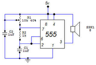
This circuit is based around the 555 timer circuit, used as an astable (free running) oscillator. The frequency (pitch) of the tone is set by the resistors and capacitors in the left side of the circuit. The first one...
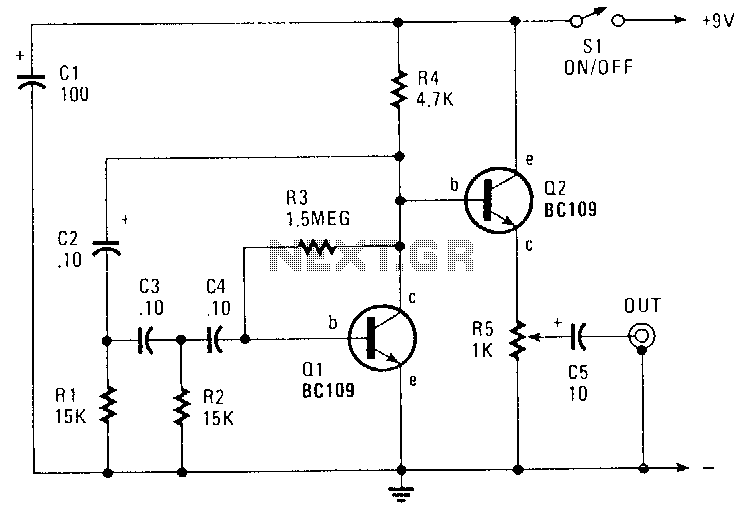
This circuit generates a sinusoidal output of approximately 8 V peak-to-peak, which can be adjusted down to zero, operating at a frequency of about 500 Hz. The signal is produced by a phase-shift oscillator. The described circuit utilizes a phase-shift...
This circuit generates a two-tone effect similar to the cuckoo song. It can be used for doorbells or other applications due to a built-in audio amplifier and loudspeaker. As a sound effect generator, it can be connected to external...
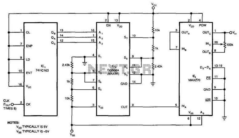
This circuit generates a pure sine wave with a total harmonic distortion (THD) of -80 dB and a frequency equal to the cutoff frequency (fc) of the filter in IC3. It utilizes a counter, an 8-channel analog multiplexer, and...