
Pure Sine-Wave Generator

The circuit's architecture is designed to ensure high fidelity in sine wave generation while minimizing distortion. The Sallen-Key topology is particularly effective for implementing the fourth-order low-pass filter, which is critical for attenuating unwanted harmonics and ensuring signal purity. The use of an 8-channel analog multiplexer allows for flexible signal routing, enabling the selection of various input signals based on the configured digital states of D0 through D6.
The choice of using resistive dividers to provide bipolar DC inputs is significant as it allows the multiplexer to handle a range of input levels, which is crucial for applications that require precise control over the output signal. The adjustable output level via the 100-kHz potentiometer provides additional versatility, accommodating different system requirements without the need for additional components.
The requirement for the clock frequency to be eight times the cutoff frequency is a critical design consideration, as it ensures that the output signal is adequately oversampled. This oversampling technique is advantageous because it reduces the complexity of the filtering process, allowing for a more straightforward implementation of the low-pass filter while maintaining the integrity of the desired sine wave output.
Overall, this circuit exemplifies a well-engineered solution for generating high-quality sine waves with minimal distortion, suitable for various applications in signal processing and waveform generation. This circuit produces a pure, - 80-dB THD sine wave with a frequency that is equal to the fc of IC3"s filter. A TT L counter, an 8-channel analog multiplexer, and a fourth-order low-pass filter can generate 1- to 25-kHz sine waves with a THD of better than - 80 dB. The circuit cascades the two second-order, continuous-time Sallen-Key filters within IC3 to implement the fourth-order low-pass filter.
Two resistive dividers connected from ground to VDD and ground to Vss provide bipolar dc inputs to the multiplexer. lb operate the circuit, you first must choose the filter"s cutoff frequency, fc, by tying IC3"s D0 through D6 inputs to 5 V or ground.
The cutoff frequency can be at 128 possible levels between 1 and 25 kHz, depending on those 7 digital input levels. Because this figure ties Z)0 through D6 to ground, fc equals 1 kHz. The 100-kHz potentiometer adjusts the output level anywhere from 1.5 V below Vdd to 1.5 V above Vss-The clock input frequency must be 8 times higher than the filter"s fc.
The multiplexer then produces an 8x oversampled staircase approximation of a sine wave. 8 oversampling greatly simplifies the smoothing requirements of the low-pass filter by pushing the first significant harmonic out to 7 the fundamental. All higher-order harmonics are removed by IC3, which includes an uncommitted amplifier for setting the output level.
Related Circuits
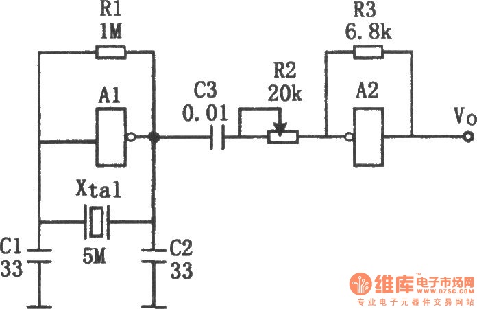
The sine wave generator composed of an inverter is illustrated in the chart. This circuit can produce a high-stability sine wave at frequencies exceeding a few megahertz. In the diagram, A1 and the crystal oscillator create an oscillating circuit,...
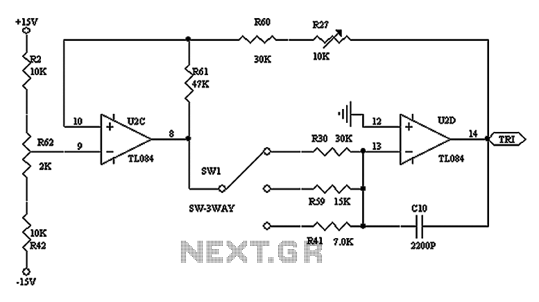
The triangular wave circuit consists of two operational amplifiers (OPs). R62 serves as the offset adjustment, while R27 is utilized for peak adjustment. A switch is included to select different resistances, allowing for the generation of triangular waves at...
PWM waveforms are frequently employed to regulate the speed of DC motors. The mark/space ratio of the digital waveform can be established either by utilizing an adjustable analog voltage level (as seen in a NE555-based PWM generator) or through...
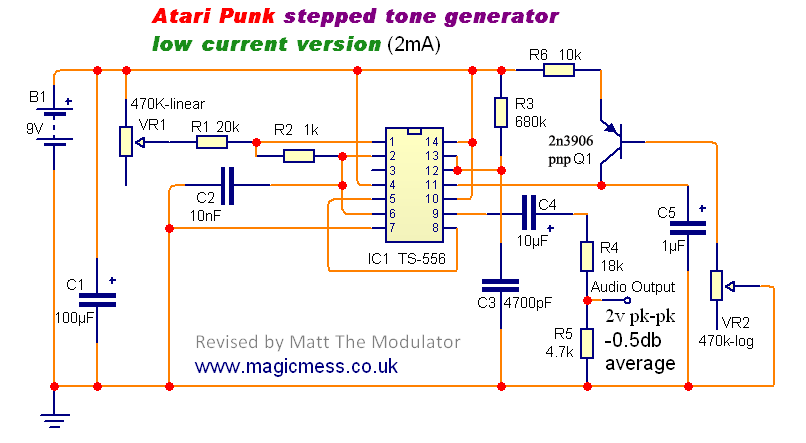
The Stepped Tone Generator is a dual oscillator circuit that produces a single pulse wave output. The first oscillator controls the pitch of the output oscillator, which divides the pitch into progressively smaller amounts based on its pulse width...
Maxim's MAX038 function generator chip is capable of producing nearly constant amplitude sine, square, and triangle waves with a low output impedance, from a very low frequency to more than 20 MHz. Basically, a function generator on a chip....
This circuit uses a UM3561 IC to produce four different sound effects. Nothing too complicated here. The IC produces all the sound effects, the output at Pin 3 being amplified by the transistor. A 64 ohm loudspeaker can be...