
tone decoder
The dual time constant tone decoder circuit is designed to optimize the performance characteristics required for specific applications, particularly in communication systems where signal fidelity and quick response to tone changes are paramount. The operational principle relies on the dynamic switching of capacitors to manipulate the filter characteristics based on the presence of input signals.
Capacitor C2 serves as the primary filter element when no tone is detected, ensuring a rapid response time due to its minimized capacitance, which allows for quick charge and discharge cycles. This characteristic is essential in applications where swift detection of tone signals is necessary to maintain system responsiveness.
Upon the detection of a tone signal, transistor Qj is activated, resulting in the integration of capacitor C'2 into the circuit. This capacitor, which can be significantly larger than C2, effectively reduces the overall cutoff frequency of the low-pass filter, thus narrowing the bandwidth. The ability to adjust the bandwidth dynamically is particularly advantageous in environments with varying signal conditions, enabling the circuit to filter out unwanted noise while maintaining the integrity of the desired tone signal.
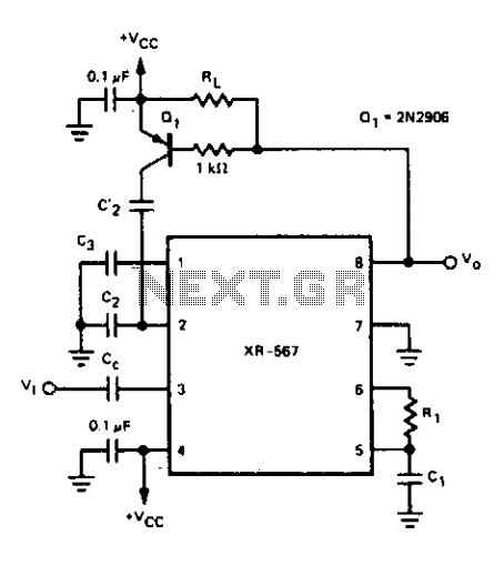
The design of the dual time constant tone decoder circuit exemplifies a sophisticated approach to signal processing, where the interplay between capacitors allows for tailored filtering characteristics that can adapt to the demands of different applications. This adaptability is crucial in ensuring effective communication in various electronic systems, from simple tone detection to complex communication protocols.For some applications it is important to have a tone decoder with narrow bandwidth and fast response time. This can be accomplished by the dual time constant tone decoder circuit shown. The circuit has two low-pass loop filter capacitors, C2 and C'2. With no input signal present, the output at pin 8 is high, transistor Qj is off, and C'2 is switched out of the circuit.
Thus, the loop low-pass filter is comprised of C2, which can be kept as small as possible for minimum response time. When an in-band signal is detected, the output at pin 8 will go low, will turn on, and capacitor C'2 will be switched in parallel with capacitor C2.
The low-pass filter capacitance will then be C2 + C'2. The value of C'2 can be quite large in order to achieve narrow bandwidth. During the time that no input signal is being received, the bandwidth is determined by capacitor C2. 🔗 External reference
Related Circuits
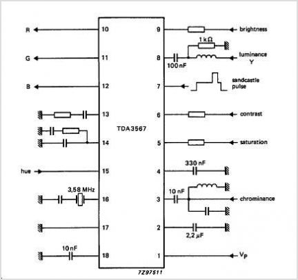
The TDA3592A transcoder circuit converts SECAM input signals into true PAL signals and can be used in combination with all types of PAL decoders by NXP Semiconductors. The TDA3592A is a versatile transcoder integrated circuit designed to facilitate the conversion...
This preamplifier was designed as a stand-alone portable unit, useful to control the signals generated by guitar pick-ups, particularly the contact "bug" types applied to acoustic instruments. Obviously it can be used with any type of instrument and pick-up....
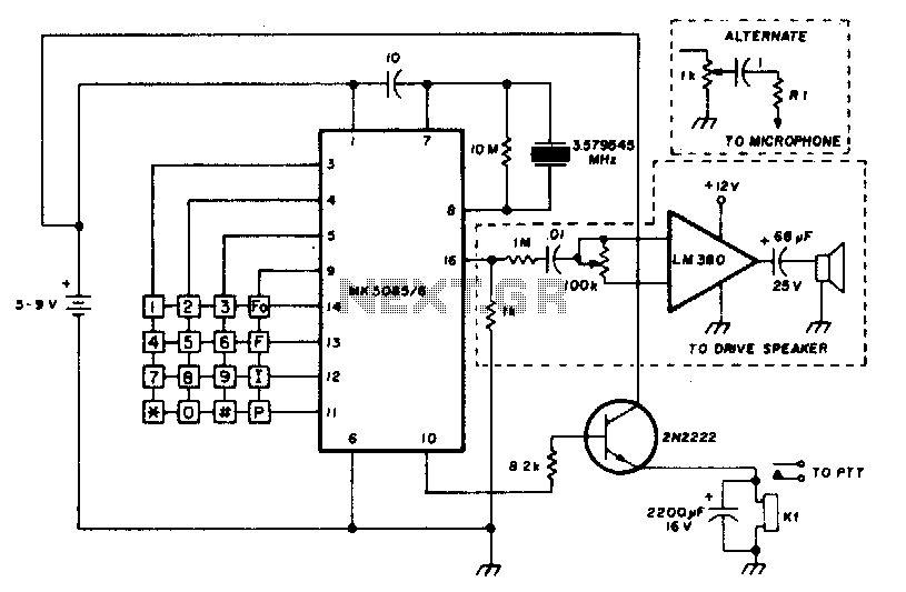
The circuit requires a minimum number of components and utilizes a low-cost standard 379.545 MHz television color-burst crystal. The speaker can be omitted, allowing the output to be directly connected to the microphone input of a transmitter. The circuit design...
The output of this circuit will be activated when a mix of two tones or frequencies is detected at the input. The frequency, denoted as f, is determined by the values of resistor R1 and additional components. This circuit is...
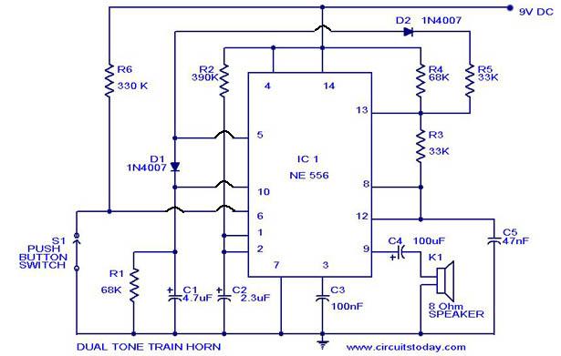
A dual-tone model train horn/sound generator/simulator circuit can be created using two NE 555 timers connected in cascade. However, the circuit diagram presented is designed with the NE 556 integrated circuit, which essentially comprises two 555 timers in a...
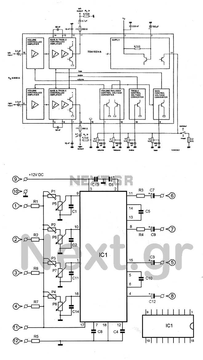
The circuit utilizes the TDA1524 chip, which is an integrated control unit for volume, bass, treble, and balance adjustments. Control is achieved through four potentiometers (P5-P8). The integrated circuit IC1 requires very few external components to operate. Potentiometers P1-P4...
Warning: include(partials/cookie-banner.php): Failed to open stream: Permission denied in /var/www/html/nextgr/view-circuit.php on line 713
Warning: include(): Failed opening 'partials/cookie-banner.php' for inclusion (include_path='.:/usr/share/php') in /var/www/html/nextgr/view-circuit.php on line 713