
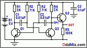
multivibrator astable
Parts and materials:
- B1 - Battery, 5 Volt
- C1 - Capacitor 0.01 µF, 15V, Film or Disc
- C2 - Capacitor 0.01 µF, 15V, Film or Disc
- C3 - Capacitor 0.1 µF, 15V, Disc
- Q1, Q2, Q3 - Transistor, 2N3904, NPN, or 2N2102
- R1, R4 - Resistor, 2K, 5%, 1/4W, CC
- R2, R3 - Resistor, 71K, 5%, 1/4W, CC
- R5 - Resistor, 100K, 5%, 1/4W, CC
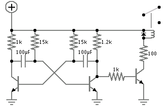
The astable multivibrator circuit is advantageous for its simplicity and versatility in generating clock signals for various digital applications. The output waveform characteristics can be tailored by adjusting the resistor and capacitor values, allowing the designer to achieve specific frequency and duty cycle requirements. The use of transistors as active elements ensures efficient operation, particularly in low-power applications. The circuit's design is robust, providing stable oscillation while minimizing the risk of overheating and excessive power consumption. Moreover, the inclusion of a buffer stage enhances the circuit's performance by ensuring that the oscillator's output remains unaffected by variations in load conditions, making it suitable for interfacing with other digital logic components. Overall, this astable multivibrator circuit serves as an excellent foundational design for generating reliable clock signals in electronic systems.The astable multivibrator is a unique form of the relaxation oscillator in which the in-phase feedback is provided by a separate transistor. The first multivibrator was built with vacuum tubes and the circuit was very popular from the start. Millions were built and used in the earliest computers and employed in TV sets in their sweep generation an
d deflection circuits. Multivibrators generate rectangular waveforms that can also be used for timing generator applications. There is often a need to have a clock oscillator when working with digital logic. Most often complete IC (Integrated Circuit) modules are used or some logic gates for that purpose. Making the clock oscillator from available spare transistors and a handful of surplus parts not usually done because of needless worry of possible circuit complexity.
As demonstrated here the circuit is quite simple and it is very easy to customize it for the application at hand. Almost any transistor available is useable in this circuit if the selected frequency for oscillation is not very high.
With the values as indicated on the schematic diagram the oscillators frequency is 1 kHz and the cycle time is mSec (mili-Second). With the circuit operating from a 5-volt power supply the output voltage is acceptable to drive TTL and CMOS gates directly.
The actual multivibrator oscillator circuit is made up of transistors Q1 and Q2 only for its operation - Figure 1. To be able to obtain the signal from this oscillator without changing its frequency with the external load, transistor Q3 is added as a buffer output amplifier stage.
The Q3 transistor isolates the multivibrator and this stage has no voltage gain as it is used for impedance transformation. Transistor Q3 provides low impedance output for the load while presenting high input impedance for transistor Q2.
Both the Q1 and Q2 transistors of this circuit work as saturated devices with reduced power dissipation and heat stress. The timing elements of this oscillator are the R2 and R3 resistors and the C1 and C2 capacitors. The design can be changed; scaled up or down easily. By using a 0. 1 uF (micro-Farad) capacitors in place of the present values in C1 and C2 the oscillator frequency would slow down by about ten.
Changing R2 and R3 such that their product stays the same changes the duty cycle of the waveform. The oscillator`s duty cycle is set to 50% - Figure 2. If R1 decreases to 22K and R3 increases to 120K the frequency stays the same but the duty cycle changes to make the resultant wave a narrow pulse. If a dual 75K potentiometer (dual 100K with paralleled resistors) is used and wired such that while one resistor increases the other decreases the frequency will stay the same while the duty cycle would adjust smoothly.
Parts and materials: B1 - Battery, 5 Volt C1 - Capacitor 0. 01 uF, 15V, Film or Disc C2 - Capacitor 0. 01 uF, 15V, Film or Disc C3 - Capacitor 0. 1 uF, 15V, Disc Q1, Q2, Q3 - Transistor, Transistor, 2N3904, NPN, or 2N2102, HS Switch R1, R4 - Resistor Resistor, 2K, 5%, 1/4W, CC R2, R3 - Resistor 71K, 5%, 1/4W, CC R5 - Resistor 100K, 5%, 1/4W, CC 🔗 External reference
Related Circuits
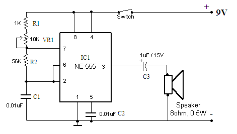
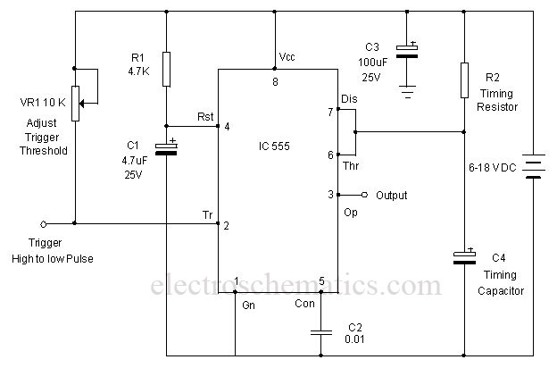
Function: to trigger a device or operate in free-running mode. Components: Battery, Charger, Battery Connector, Capacitor, Integrated Circuit (IC), Resistor VR1-10K, Resistor R1-1K, Resistor R2. The described circuit functions either to trigger a connected device or to operate in a...
An oscillator circuit of this nature is often utilized as a clock circuit. This circuit employs a crystal frequency control with a stability of one million hertz. An oscillator circuit designed for clock applications typically generates a periodic signal, which...
A CMOS timer generates true square waves because, unlike the bipolar 555, its output swings from rail to rail. The component values shown give a frequency of about 400 Hz. The CMOS timer circuit operates by utilizing complementary metal-oxide-semiconductor technology...

The 555 timer integrated circuit (IC) is an exceptionally versatile component utilized in various applications, including generating clock pulses, switch debouncing, and functioning as an output transducer. The standard 555 IC is packaged in an 8-pin configuration, available in...
A monostable multivibrator using the IC CD4538 is a precision device that functions as a monostable/astable multivibrator and is designed to avoid false triggering. This IC is suitable for various applications requiring precise timing cycles. The CD4538 offers improved...
Powering this circuit with a 6V alkaline battery operates effectively with 100µF capacitors. However, there is an issue when attempting to replace the LED with a DPDT relay; a 6V relay previously available does not activate. Additionally, when using...
Warning: include(partials/cookie-banner.php): Failed to open stream: Permission denied in /var/www/html/nextgr/view-circuit.php on line 713
Warning: include(): Failed opening 'partials/cookie-banner.php' for inclusion (include_path='.:/usr/share/php') in /var/www/html/nextgr/view-circuit.php on line 713