
Multivibrator circuit

The 555 timer IC can be configured in various modes, including monostable and astable modes, allowing for a wide range of applications. In astable mode, the circuit continuously oscillates between high and low states, generating a square wave output. This output can be used to drive LEDs, generate audio tones, or serve as a timing signal for other digital circuits. The frequency of oscillation is determined by the values of the resistors and capacitor used in the circuit, which can be calculated using the formula:
\[ f = \frac{1.44}{(R1 + 2R2)C1} \]
Where \( f \) is the frequency in hertz, \( R1 \) and \( R2 \) are in ohms, and \( C1 \) is in farads. The mark-space ratio can be adjusted based on the resistor values, allowing for customization of the output waveform characteristics. The addition of a diode in the alternative configuration simplifies the calculation of the mark-space ratio by isolating R2 from the charging cycle of C1, thus providing a more stable output.
In practical applications, the 555 timer is often incorporated into larger systems, such as timers, pulse-width modulation controllers, and frequency generators. Its ability to function across a wide voltage range and its relatively low cost make it a popular choice among engineers and hobbyists alike. The 555 timer IC's robust design ensures reliability in various environments, making it suitable for both prototyping and production applications.The 555 timer IC is a very versatile and useful component and can be used for many things, from giving clock pulses to switch debouncing and as an output transducer. The basic 555 IC is housed in an 8-pin carrier, and these come in DIL and SOIC formats. They run from 3-15V, and are generally quite hardy devices. The frequency and mark-space ratio are defined by the values of R1, R2 and C1 only. For a roughly even (1:1) mark-spce ratio, R1 is usually set at 1K, and the other resistor (R2) and capacitor are changed to alter the frequency. If better control over the mark-space ratio is required, use the next circuit. This variation allow much easier control of the mark-space ratio without too much impact on the frequency.
The only difference is a diode petween Pins 6 and 7, with the cathode at Pin 6. The effect of this is to shunt resistor R2 when charging C1. This means that C1 charges though R1 only. This removes R2 from the "high-time" equation, and make calculating the mark-space ratio easier and prevents the frequency from being altered excessively by changes in the mark-space ratio ( although this still happens to a certain extent). This astable uses fewer components than the basic astable, and requires only the IC, one resistor and one capacitor, plus the Pin 5 capacitor for final versions.
This astable has a MSR of approximately 1:1, but this tends to increase under heavy current load, as the output does not swing fully to the power supply. This astable is not a reliable source of frequency, and should never be used where an accurate, stable clock is needed.
Pin 4 is normally held high, and in this state it does nothing. However, when Pin 4 is brought low, the 555 is disabled, and the output is held low. This can be used to turn an astable on when desired. An example of this is the double-astable bleeper, which uses the output from one astable to enable another, faster astable. The units that the components values and frequency are measure in are the standard base units: ohms, farads and hertz.
This are often inconvenient, as the value for componets are usually several orders of magnitude away from the base unit. It is possible to use more conveninet units to calculate the frequency, and the common combinations are given below: This plugin consists of a single 555 Astable.
This plugin is very versatile, and can be used for any number of things, but it often is used to give a clock to run a circuit. The plugin below gives a pulse of about 2Hz with a very low mark-space ratio. The circuit diagram is given below. 🔗 External reference
Related Circuits
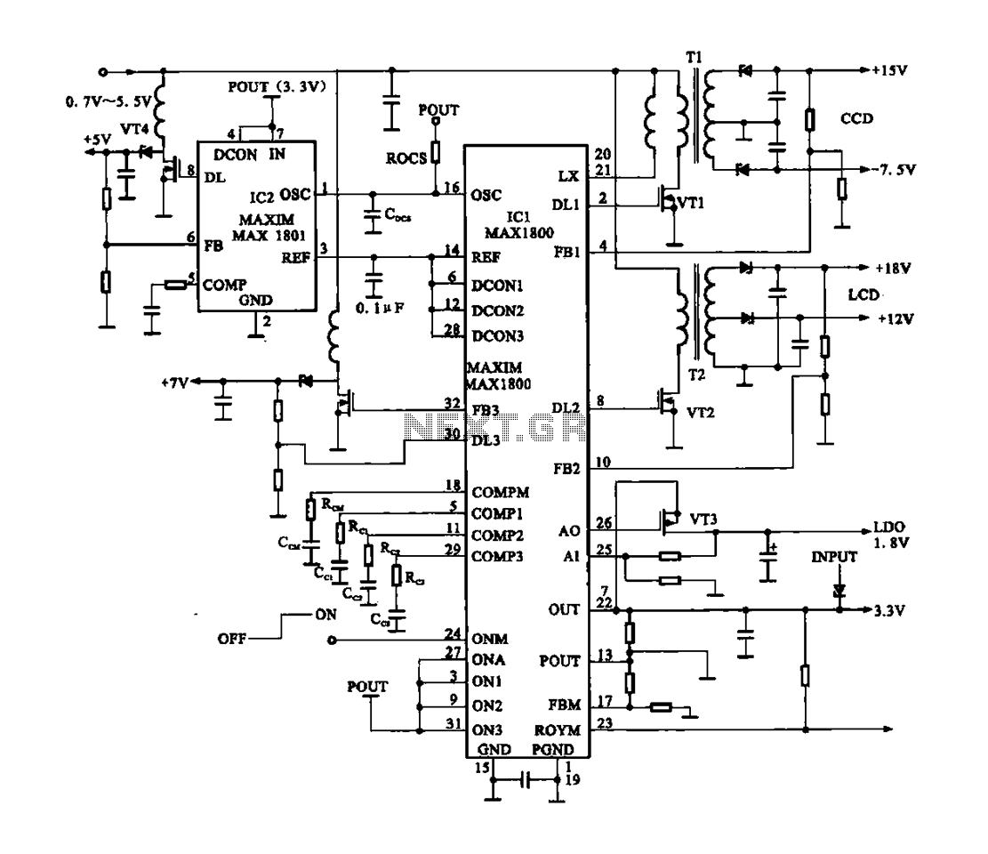
Digital Cameras - DV machine power supply circuit. This circuit utilizes the MAX1800 chip to manage the power supply for digital cameras and DV machines. Digital cameras are typically battery-operated and require low voltages ranging from 0.7 to 5.5...
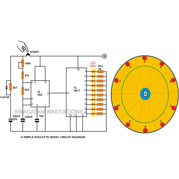
A simple circuit for a 10 LED roulette wheel is presented. Pressing the button initiates the LEDs in a rotational sequence that starts at full speed and gradually decelerates until it halts at a randomly selected LED. The randomness...
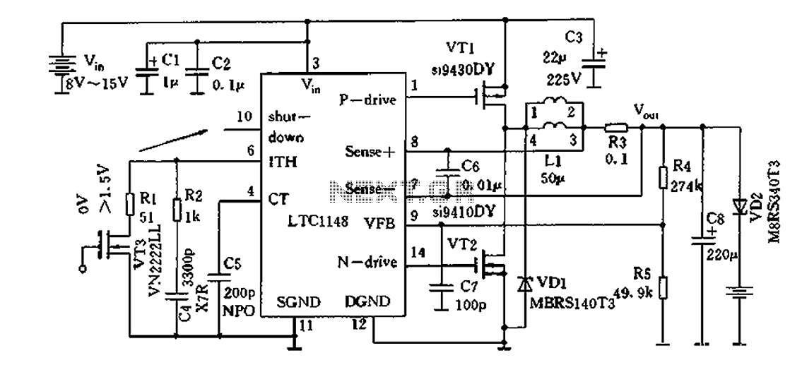
Efficient nickel-cadmium battery charger IC (LTC1148) circuit The LTC1148 is an integrated circuit designed for the efficient charging of nickel-cadmium (NiCd) batteries. This charger IC features a constant current/constant voltage (CC/CV) charging method, which is essential for optimizing the charging...
Have you ever seen the stairs to one of the upper stories in your house turn into a waterfall? Or maybe you've come home to find your aquarium fish trying to... The provided description suggests a scenario involving unexpected water...
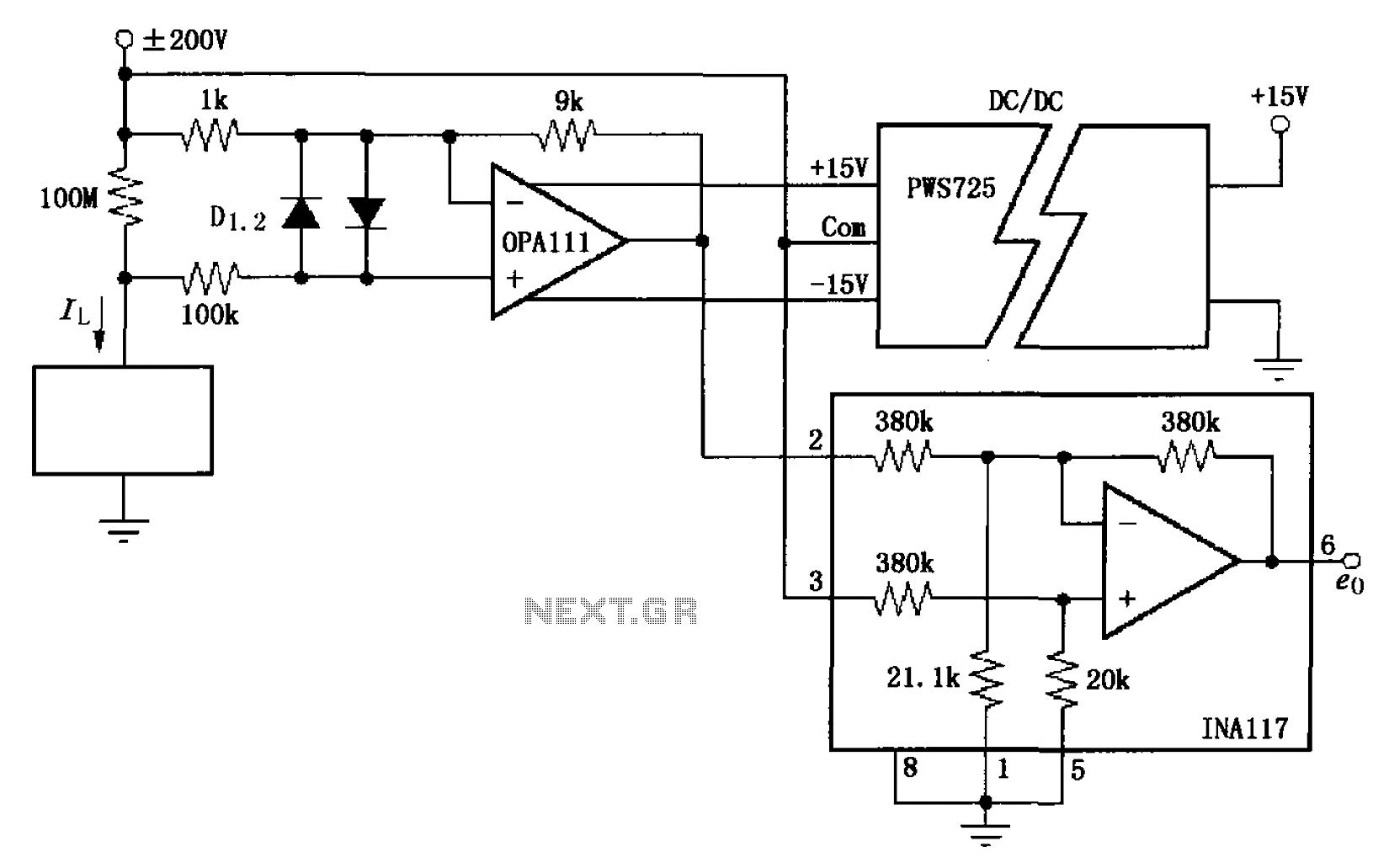
The circuit illustrated in FIG OPA111 is designed for measuring input buffer leakage current. The transistors D1 and D2, which are 2N3904 types, short the base and collector contacts while leaving the emitter open. When a power supply of...
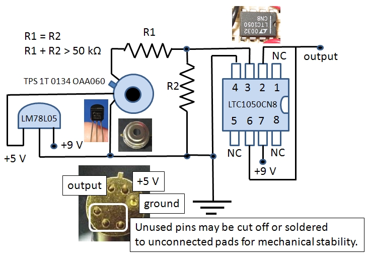
The Excelitas TPS 1T 0134 OAA060 thermopile sensor is a self-contained module that includes a built-in operational amplifier. The designation A2TPMI 334 OAA 60 is used in this document due to its previous identification under the PerkinElmer part number...
Warning: include(partials/cookie-banner.php): Failed to open stream: Permission denied in /var/www/html/nextgr/view-circuit.php on line 713
Warning: include(): Failed opening 'partials/cookie-banner.php' for inclusion (include_path='.:/usr/share/php') in /var/www/html/nextgr/view-circuit.php on line 713