
Muscular Bio-Stimulator
IC1 serves as the pulse generator, producing short-duration pulses essential for the operation of the circuit. The output frequency of approximately 80Hz is suitable for therapeutic applications, particularly in electrotherapy. Q1, as a buffer, ensures that the pulse signal is stable and adequately drives the subsequent components without distortion. Q2, functioning as an inverter, alters the polarity of the pulse, which is crucial for the operation of the transformer T1.
The transformer T1 is a critical component, converting the low voltage output from the circuit to a higher voltage suitable for therapeutic applications. The specifications of T1 indicate it can handle 220V input, stepping down to 12V output at a current rating of 100 to 150mA. The reverse connection of the transformer is essential to ensure proper operation and safety in the circuit.
The user interface, primarily through potentiometer P1, allows for fine control over the output pulse amplitude. The visual feedback provided by LED D1 aids the user in adjusting the settings to a comfortable level, ensuring a safe and effective treatment experience. The inclusion of protective diode D2 is vital in safeguarding Q2 from high voltage spikes that may occur during the switching process, thereby enhancing the reliability of the circuit.
Electrode application is an important aspect of the design, and the use of small metal plates ensures effective contact with the skin. The option to moisten the electrodes can improve conductivity, which is beneficial for the therapeutic effects intended. The design also incorporates safety features, such as the linking of SW1 to P1, which mitigates the risk of sudden voltage application to the user.
For scalability, the circuit allows for multiple output electrodes, accommodating a variety of treatment modalities. The provision for a timer enhances the usability of the device, allowing for controlled treatment sessions. Overall, this circuit design is well-suited for applications in electrotherapy, providing a customizable and safe user experience.IC1 generates 150 µSec. pulses at about 80Hz frequency. Q1 acts as a buffer and Q2 inverts the polarity of the pulses and drives the Transformer. The amplitude of the output pulses is set by P1 and approximately displayed by the brightness of LED D1. D2 protects Q2 against high voltage peaks generated by T1 inductance during switching. T1 is a small mains transformer 220 to 12V @ 100 or 150mA. It must be reverse connected i. e. the 12V secondary winding across Q2 Collector and negative ground, and the 220V primary winding to output electrodes. In any case P1 should be operated by the "patient", starting with the knob fully counter-clockwise, then rotating it slowly clockwise until the LED starts to illuminate.
Stop rotating the knob when a light itch sensation is perceived. In some cases a greater pulse duration can be more effective in cellulite treatment. Try changing R2 to 5K6 or 10K maximum: stronger pulses will be easily perceived and the LED will shine more brightly. Electrodes can be obtained by small metal plates connected to the output of the circuit via usual electric wire and can be taped to the skin.
In some cases, moistening them with little water has proven useful. SW1 should be ganged to P1 to avoid abrupt voltage peaks on the "patient`s" body at switch-on, but a stand alone SPST switch will work quite well, provided you remember to set P1 knob fully counter-clockwise at switch-on. Some commercial sets have four, six or eight output electrodes. To obtain this you can retain the part of the circuit comprising IC1, R1, R2, C1, C2, SW1 and B1. Other parts in the diagram (i. e. P1, R3, R4, D1, D2, Q2 & T1) can be doubled, trebled or quadrupled. Added potentiometers and R3 series resistors must be wired in parallel and all connected across Emitter of Q1 and positive supply.
Commercial sets have frequently a built-in 30 minutes timer. For this purpose you can use the Timed Beeper the Bedside Lamp Timer or the Jogging Timer circuits available on this Website, adjusting the timing components to suit your needs. 🔗 External reference
Related Circuits
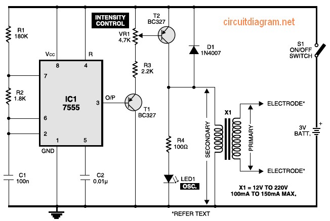
Figure 1 shows the circuit of a muscular stimulator. The IC 7555 is configured as an astable multivibrator to generate approximately 80Hz pulses. The output from IC1 is connected to transistor T1, whose emitter is linked to the base...

The Bio-Stimulator provides muscle stimulation and invigoration, primarily serving as an aid in reducing cellulitis. Electrodes should be affixed to the skin at both ends of the selected muscle, and the P1 knob should be rotated slowly until a...

This is a small, portable set, designed for those aiming at look improvement. The Bio-Stimulator provides muscles stimulation and invigoration but, mainly, it could be an aid in removing cellulite. Tape the electrodes to the skin at both ends...

SW1 should be connected to P1 to prevent sudden voltage spikes on the patient's body during switch-on. However, a standalone SPST switch can also be effective, as long as the P1 knob is set fully counter-clockwise upon activation. Some...