
Muscular Bio-Stimulators

The Bio-Stimulator circuit is designed to facilitate safe and effective muscle stimulation, specifically targeting the treatment of cellulitis. The core of the circuit is the integrated circuit IC1, which generates precise pulse signals essential for muscle contraction. The configuration of Q1 and Q2 ensures that the generated pulses are buffered and inverted, allowing for effective driving of T1, the transformer that steps down the mains voltage to a safe level for application on the skin.
The choice of T1 as a small mains transformer is critical, as it provides the necessary voltage reduction while maintaining current capacity. The reverse connection of the transformer is pivotal to ensure that the output electrodes receive the correct polarity of the pulses, which is essential for effective stimulation. The feedback mechanism provided by LED D1 offers visual confirmation of the output signal's amplitude, allowing the user to adjust the intensity of stimulation based on personal comfort.
The inclusion of D2 serves as a protective measure against voltage spikes, ensuring that Q2 operates within safe limits, thereby enhancing the longevity and reliability of the device. The adjustable resistor R2 allows for customization of the pulse duration, providing flexibility in treatment intensity. Users can experiment with different resistor values to find the optimal setting that yields the best results for their specific needs.
The electrode design is crucial for effective therapy. Utilizing metal plates connected via standard wiring ensures good conductivity and effective signal transmission to the skin. The option to moisten the electrodes can further enhance conductivity, improving the overall efficacy of the treatment.
SW1's integration with P1 is a thoughtful design choice, mitigating the risk of sudden voltage application that could cause discomfort or harm to the user. This safety feature, combined with the operational guidelines for starting the device, underscores the importance of user safety in the design.
For users seeking enhanced functionality, the ability to expand the number of output electrodes provides versatility. By retaining and replicating specific components of the circuit, users can customize the Bio-Stimulator to accommodate larger treatment areas or multiple muscle groups simultaneously. The option to incorporate a timer adds convenience, ensuring that treatments are administered for the recommended duration without requiring constant supervision.
Overall, the Bio-Stimulator circuit exemplifies a well-thought-out design catering to both therapeutic effectiveness and user safety, making it a valuable tool for muscle stimulation and cellulitis treatment.The Bio-Stimulator provides muscles` stimulation and invigoration but, mainly, it`s an aid in removing cellulitis. Tape the electrodes to the skin at both ends of the chosen muscle and rotate P1 knob slowly until a light itch sensation is perceived.
Each session should last about 30 - 40 minutes. IC1 generates 150 µSec. pulses at about 80Hz frequency. Q1 acts as a buffer and Q2 inverts the pulses` polarity and drives the Transformer. Output pulses` amplitude is set by P1 and approximately displayed by LED D1 brightness. D2 protects Q2 against high voltage peaks generated by T1 inductance during switching. T1 is a small mains transformer 220 to 12V @ 100 or 150mA. It must be reverse connected i. e. : the 12V secondary winding to Q2 Collector and ground, and the 220V primary winding to output electrodes. In any case P1 should be operated by the "patient", starting with the knob fully counter-clockwise, then rotating it slowly clockwise until the LED starts to illuminate.
Stop rotating the knob when a light itch sensation is perceived. In some cases a greater pulse duration can be more effective in cellulitis treatment. Try changing R2 to 5K6 or 10K maximum: stronger pulses will be easily perceived and the LED will shine more brightly. Electrodes can be obtained by small metal plates connected to the circuit`s output via usual electric wire and can be taped to the skin.
In some cases, moistening them with little water has proven useful. SW1 should be ganged to P1 to avoid abrupt voltage peaks on the "patient`s" body at switch-on, but a stand alone SPST switch works quite well, provided you remember to set P1 knob fully counter-clockwise at switch-on. Some commercial sets have four, six or eight output electrodes. To obtain this you can retain the part of the circuit comprising IC1, R1, R2, C1, C2, SW1 and B1. Other parts in the diagram (i. e. P1, R3, R4, D1, D2, Q2 & T1) can be doubled, trebled or quadrupled. Added potentiometers and R3 series resistors must be wired in parallel and all connected from Emitter of Q1 to positive supply.
Commercial sets have frequently a built-in 30 minutes timer. For this purpose you can use the Timed Beeper the Bedside Lamp Timer or the Jogging Timer circuits available in this Website, adjusting the timing components to suit your needs. 🔗 External reference
Related Circuits

This is a small, portable set, designed for those aiming at look improvement. The Bio-Stimulator provides muscles stimulation and invigoration but, mainly, it could be an aid in removing cellulite. Tape the electrodes to the skin at both ends...

SW1 should be connected to P1 to prevent sudden voltage spikes on the patient's body during switch-on. However, a standalone SPST switch can also be effective, as long as the P1 knob is set fully counter-clockwise upon activation. Some...
IC1 generates 150 µSec pulses at approximately 80Hz frequency. Q1 functions as a buffer, while Q2 inverts the pulse polarity and drives the transformer. The output pulse amplitude is adjusted by P1 and is visually indicated by the brightness...
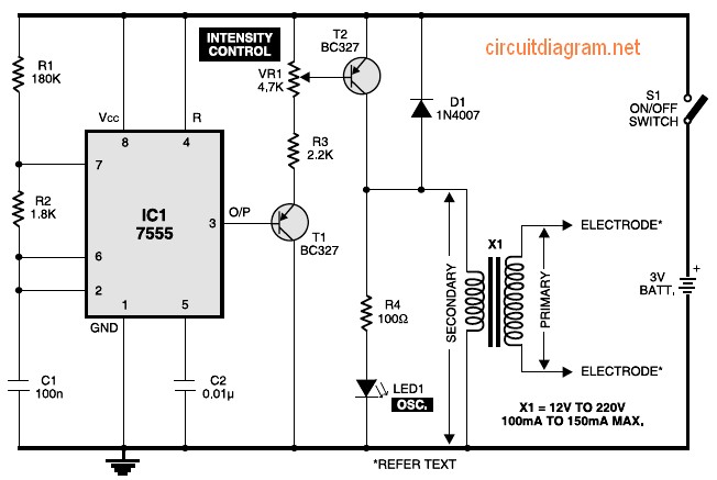
Figure 1 shows the circuit of a muscular stimulator. The IC 7555 is configured as an astable multivibrator to generate approximately 80Hz pulses. The output from IC1 is connected to transistor T1, whose emitter is linked to the base...