
pic micro multiple servo motor
The circuit described involves a microcontroller-based system designed for controlling servomotors through pulse width modulation (PWM). The primary components include a microcontroller capable of generating PWM signals, a dual-servo configuration, and an RS-232 interface for programming and communication. The two pulse width variables, pw1 and pw2, are essential for managing the positions of the servos, with specific routines assigned for each direction of rotation.
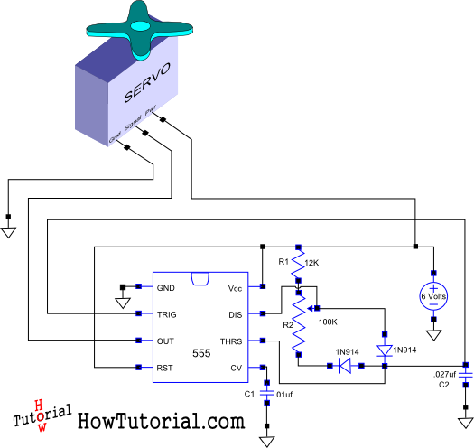
The first servo is wired according to a previously established circuit design, ensuring compatibility and ease of integration. The second servo's configuration utilizes B3 for its pulse output, while B4 and B5 facilitate the operation of a single-pole double-throw (SPDT) switch, allowing for versatile control of the servomotor's direction. The program logic dictates that the servomotor sweeps from an initial counterclockwise position to a clockwise position, demonstrating the full range of motion.
The pulse width control variable, pw, initiates at a value corresponding to the extreme left position of the servo, translating to -45 degrees. The program incrementally increases this value until the servo reaches the extreme right position at 45 degrees, effectively reversing the direction of rotation. This functionality illustrates the basic principles of servo control using the PIC Basic language, providing a clear example of PWM in action.
The programmer's architecture is powered by an RS-232 interface, operating within specified voltage levels, which is critical for ensuring reliable communication with the microcontroller. The programmer supports a wide range of PIC microcontroller families, facilitating flexibility in application. The inclusion of In-Circuit Serial Programming (ICSP) allows for direct programming of microcontrollers while they are installed in the circuit, enhancing convenience and efficiency.
The software associated with the programmer is designed for compatibility across multiple operating systems, ensuring broad usability. The modem check feature is a critical safeguard, preventing accidental programming errors that could arise from misconfigured connections. Furthermore, the ability to program multiple chips simultaneously and optimize communication parameters based on cable length enhances the system's efficiency, making it suitable for various applications in electronics development.
In summary, this circuit exemplifies an effective implementation of servo control using PWM, supported by a robust programming interface, making it a valuable resource for electronics engineers and hobbyists alike.The program uses two pulsewidth variables, pw1 and pw2; and two sets of routines, left1 and left2, right1 and right2; one for each motor. As you can see in the schematic, the first servo is wired as per the previous circuit. The second servo is now using B3 as it`s pulse out, and B4 and B5 for the SPDT switch. sweep the servomotor from CCW to CW a nd then sweep back. The program will be kept simple as to demonstrate the priniciples of controlling a servo with a the PIC Basic language. The variable pw controls the pulsewidth, and is started at 100 (extreme left, -45 degrees). The program sends the pulse out to the servo, and then is increased by a value of 1 until it reaches 200 (extreme right, 45 degrees), at which point it will reverese the rotation.
This Programmer is powered by the RS-232 and it works with RS-232 levels at only < ±8. 6V. It programs PIC12C5XX, 12C67X, 24CXX, 16C55X, 16C61, 16C62X, 16C71, 16C71X, 16C8X, 16F8X and ISO-CARD`s with ASF. Other serial programmable chips by adapter. The Programmer supports ICSP, In-Circuit Serial Programming. Features: Utilities now work on Dos, Windows 3. 1, Windows 95, Windows 98 and are expected to work on all other operating systems. All software does modemcheck to ensure that modems flash are not programmed by programmer, e. g. if you forgot to swap cable between programmer and modem. It is now possible to program more chips at same time using more of the communication port`s while multitasking under Windows.
The software automatic optimize delay for cable length and works with modem cables up to 100m. It use the RS232 controler chip only, and does not invoke use of other timers. Also short programming pulses are now hardware controled. Laptops only tested with PIC16C8x and 24Cxx. 🔗 External reference
Related Circuits

Introduction The ignition timing lights commonly used range from simple neon to complex units. Neon timing lights have a drawback due to their low light output, necessitating operation in subdued lighting. This presents a safety hazard, as users tend...

The project involves the design of a custom multiplexer for a four-channel oscilloscope, allowing for simultaneous display of multiple figures with distinct X/Y inputs. The instrument is intended to enhance the functionality of existing oscilloscopes, particularly in conjunction with...

The camera rotator circuit uses a 2716 EPROM to store a table of logic values that control the motor driver (H-bridge) circuit. The EPROM data is shown in the schematic. By using the EPROM, a large number of discrete...

NOPPP is a straightforward programmer designed for the PIC16C84, PIC16F83, and PIC16F84(A) microcontrollers. It connects to the parallel port of a PC. Plans for this device were published in a magazine. The NOPPP programmer is an essential tool for developers working...

The A3952S stepper motor controller, designed by Allegro MicroSystems, can be utilized to create a straightforward and effective motor driver circuit suitable for various electronic applications. This controller supports continuous output currents of up to 2 A and operates...
This document outlines the design of a simple circuit that enables control of a servo motor and allows for testing its functionality. The circuit for controlling a servo motor typically consists of a microcontroller, a power supply, and the servo...