
Nature simulator with 555 circuit
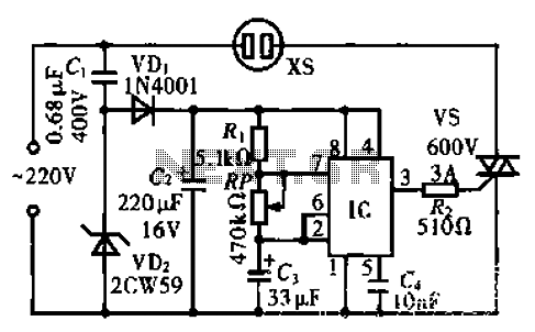
The circuit described utilizes the NE555 timer IC in its astable mode, which is a popular configuration for generating continuous square wave signals. In this setup, the timing components, which include resistors R and RP and capacitor C3, determine the frequency and duty cycle of the output waveform. The output signal from pin 3 of the NE555 is a square wave that alternates between high and low states at a frequency defined by the values of R, RP, and C3.
The current-limiting resistor R2 is crucial as it protects the TRIAC from excessive current that could otherwise damage it. The TRIAC, a semiconductor device that can control AC loads, is connected to the output to manage the power supplied to the fan. When the NE555 outputs a high signal, the TRIAC is triggered, allowing current to flow to the fan. Conversely, when the signal is low, the TRIAC turns off, interrupting the current flow and stopping the fan.
This circuit is particularly useful for applications requiring fan control based on specific timing intervals. By adjusting the values of R, RP, and C3, the frequency of the oscillation can be modified, thus changing how frequently the fan operates. This flexibility makes the circuit suitable for various cooling and ventilation applications, where intermittent fan operation is desired to save energy or manage temperature effectively. Proper heat dissipation measures should be considered in the design to ensure reliable operation of the TRIAC and the overall circuit.Circuit works: an integrated circuit lC (NE555) and R, RP, C3 substandard elements constituting around astable multivibrator, lC 3 feet square wave oscillation signal output from the current limiting resistor R2 is added to the TRIAC vs the control terminal, connected to the outlet to control the fan inside xs make it work according to the oscillation signal intermittently
Related Circuits

This is a simple frequency counter designed to monitor the 240VAC mains supply. It has a frequency range of 0-999Hz, making it suitable for use with 400Hz equipment as well. Standard TTL/CMOS logic is utilized for the counters and...
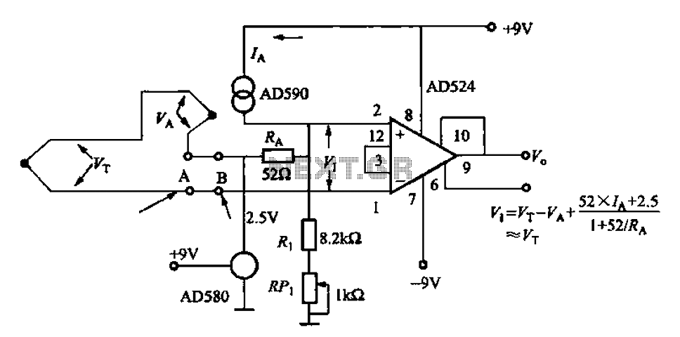
The AD524J type thermocouple cold junction temperature compensation circuit is illustrated in Figure 1-20. This circuit utilizes J-type thermocouples, with the base reference voltage sourced from the AD580, an integrated temperature sensor, and the precision instrumentation amplifier AD524. The...

The operational amplifier (op-amp) used in the signal meter circuit is the TL061. The LF351 can also be used interchangeably, as it has the same pin layout. For those using a TL062 or similar models, the differing pin configurations...

This inexpensive FM radio receiver antenna booster utilizes the BF324 TO92 style PNP transistor in a grounded-base configuration. The circuit can be employed as a... The FM radio receiver antenna booster circuit is designed to enhance the reception capabilities of...
This circuit diagram for a 12V inverter is simple to construct and utilizes inexpensive components that many electronics hobbyists may already possess. While it is feasible to create a more powerful circuit, the complexity arises from managing the significant...
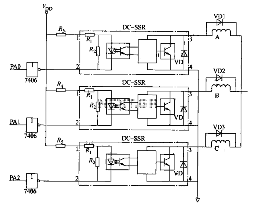
The figure illustrates that the DC Solid State Relay (SSR) in the input stage functions as an opto-isolator. When the switch output is high, the driver circuit inverts this signal to low. This process involves a light-emitting diode (LED)...