
solid state tesla coil circuit
This solid-state Tesla Coil circuit is designed to leverage a flyback transformer, which is a common component found in older television sets. The use of a 555 timer to control a single MOSFET allows for efficient operation, minimizing heat generation compared to traditional designs that utilize multiple high-power transistors. The adjustable on and off times of the circuit enable fine-tuning for optimal performance with various flyback transformers, ensuring versatility in application.
The high voltage output generated by this circuit can be substantial, exceeding 60kV, which can be further amplified with the addition of a voltage multiplier unit. The requirement for a flyback transformer without an internal rectifier is crucial, as this ensures that the transformer can function effectively within the circuit parameters. The identification of the primary and secondary connections of the transformer is essential for proper operation, and the use of an ohmmeter aids in this process.
When assembling the circuit, safety precautions are paramount due to the high voltages involved. The initial testing phase should be conducted without the flyback transformer connected, using a resistor in its place to allow for safe adjustments to the timing components. Once the circuit is configured and tested, connecting the flyback transformer should be done with caution, ensuring that all safety measures are in place to prevent accidental shocks or burns.
The design emphasizes the importance of experimentation, particularly in determining the number of turns for the primary winding if an open-frame transformer is used. Adjustments to the circuit settings should be approached methodically, with the understanding that the output can produce significant electrical discharges.
In conclusion, this solid-state Tesla Coil circuit is a sophisticated design that requires careful attention to detail during assembly and operation. The potential for high voltage output necessitates strict adherence to safety protocols, and the circuit should only be constructed by individuals with a thorough understanding of high-voltage electronics.Similar to the two transistor solid state Tesla Coil already on this site, this solid state Tesla Coil design uses a normal flyback transformer to generate it`s high voltage output. Unlike the other circuit, this one does not use two huge power transistors and high wattage resistors.
Instead it uses a 555 timer to more efficiently drive a single M OSFET. It`s waveform has adjustable off and on time, making for an efficient circuit with little waste heat. It can be adjusted to drive most commonly found flyback transformers and can operate from a 12V to 18V supply.
HV output can reach 60KV or more depending on the transformer and supply voltage. T1 as specified in the parts list is going to be almost impossible to find, but don`t worry. Penn-Tran was bought by Wiltron and no longer exists. However, most any medium to large flyback transformer will work as long as it does not have an internal rectifier. Suitable units are most often found in TVs made during the 1970s and 1980s. Look for the most impressive, dangerous, menacing transformer you can find. If you need an idea, a picture of a great transformer for use in this circuit: These can be found in a small metal box generally in the corner of the TV case, complete with a very handy voltage multiplier unit and usually a nice heatsink.
You will need to either look up the datasheet for the transformer you have, or probe it with an ohmmeter to identify the coil connections. Most flybacks have a load of taps on the HV side to provide focusing, horizontal and vertical signals.
These taps are generally of no use to you. To find the primary (coil B-A on the schematic) you need to find the two lowest resistance connections that are not also connected to the HV secondary wiring. Alternately, if your flyback has an open frame like the one in the picture, you can wind on 5 or so turns of 16 gauge magnet wire as a primary.
You will need to experiment with the number of turns to get maximum output. The HV ground lead (connection C on the schematic) is generally easy to locate. It will come from the HV secondary and be tied to the frame of the transformer or chassis ground. If by some miracle you were able to locate the Penn-Tran transformer, then connection B is the red dot on the transformer, A corresponds to the black dot, and C matches the orange dot. If the TV you salvaged the transformer from has a voltage multiplier unit (visible slightly at the far right of the above picture), then take it as well.
It can multiply the output of this circuit into very high (over 100KV) DC voltages. When building the circuit, leave the flyback disconnected. Connect a 10 Ohm 10W resistor in place of the primary of T1 and connect a scope to the collector of Q3. Adjust R4 to produce an off time of about 10 microseconds. Adjust R2 for an on time of about 70 microseconds. Now remove the scope, 10 ohm resistor, and connect up T1. Power the circuit back on and you should have a high voltage available at the output. If you do not have a scope, just set both pots in their middle position and then adjust them by trail and error until you get the biggest spark at the output of T1.
Needless to say, this circuit can produce dangerous voltage. At the very least you are looking at a painful shock. More then likely a decent burn will result from contact with the HV output, as well as instant and uncontrollable muscle contraction. If you have heart problems, don`t build this circuit. Be careful!. 🔗 External reference
Related Circuits

Very simple and useful circuit for communication between two persons. The Q1 is used to amplify the weak output signal of the speaker when one pushes his (her) side push-button to speak. The base-common configuration of the Q1 pre-amplifier...

This simple mock flasher LED simulates the indicator of a sophisticated alarm system. It can be placed in doors, gates, and vehicles to confuse intruders. The mock flasher LED circuit is designed to mimic the flashing behavior of a typical...
The Zero Volt Diode (ZVD) is a circuit useful in various applications, including solar chargers of all types. It is a novel circuit where a power MOSFET functions as a very low voltage drop diode, switching states at 0V...
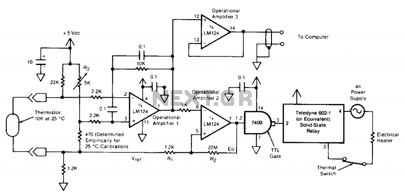
The circuit switches the current to an electrical heater on and off to maintain the temperature of a room at 25 ±0.5°C. The temperature sensor is a thermistor that provides a differential input (for reduced noise) to an operational...
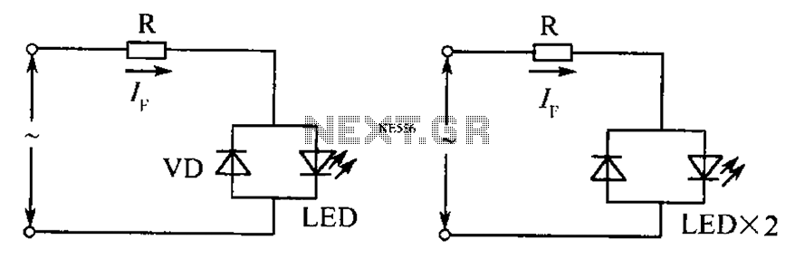
The circuit operates effectively even when the polarity of the voltage or the power supply is reversed. It functions with DC drives similar to AC drives, utilizing a current limiting resistor R. The value of this resistor is determined...

A band-stop filter (BSF) utilizing an integrated operational amplifier is designed to suppress signals within a specific frequency band, allowing signals outside this band to pass with minimal attenuation. This configuration is achieved through a two-stage network, which employs...
Warning: include(partials/cookie-banner.php): Failed to open stream: Permission denied in /var/www/html/nextgr/view-circuit.php on line 713
Warning: include(): Failed opening 'partials/cookie-banner.php' for inclusion (include_path='.:/usr/share/php') in /var/www/html/nextgr/view-circuit.php on line 713