
Economical Transistor Radio

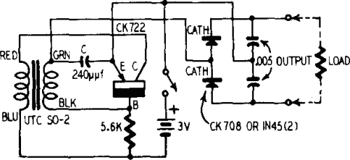
The schematic diagram presents a common-collector amplifier configuration, often referred to as an emitter follower. This design is characterized by its high input impedance and low output impedance, making it ideal for interfacing with other stages of the audio circuit. The common-collector stage does not introduce significant loading on the tuned circuit, which maintains the circuit's quality factor (Q) and enhances the frequency response. This feature is crucial for applications where sensitivity and selectivity are paramount, such as in radio receivers.
The audio amplifier's design necessitates three transistor stages due to the low supply voltage, which limits the output capabilities of each individual stage. The use of multiple stages allows for adequate amplification of the audio signal without distortion, ensuring clear sound reproduction. The potentiometer serves as a variable resistor, allowing for user-adjustable volume control, which is essential for user-friendly operation.
The internal ferrite rod antenna, with its specified dimensions and winding, is designed to optimize signal capture for the radio frequency range of interest. The 50 turns of enameled copper wire create a tuned circuit that resonates at specific frequencies, enhancing signal reception. The addition of a two-meter external wire aerial significantly improves reception capabilities, allowing the radio to access a broader range of stations.
Power efficiency is a notable feature of this radio design. With a current draw of only 10 mA, the circuit is capable of operating for extended periods on a single alkaline AA cell. This low power consumption is advantageous for portable applications, extending the usability of the device without frequent battery replacements. Overall, this schematic represents a well-engineered solution for compact, efficient audio amplification in radio applications.The schematic diagram shows an audio stage with a common-collector circuit. This does not damp the tuned circuit, but instead actually increases its response. This yields good sensitivity and selectivity. Due to the low supply voltage, the subsequent audio amplifier needs three transistor stages. The volume is adjusted using the potentiometer. Thi s radio works well using an internal ferrite rod (around 1 cm diameter and 10 cm long) with a winding of around 50 turns of enameled copper wire. With a two-meter external wire aerial, you can receive even more stations. This radio is not only economical in terms of components, it also needs very little juice`: since the current consumption is only 10mA, an alkaline AA cell will easily last for around 200 hours of operation.
🔗 External reference
Related Circuits
Using only a single transistor and a few passive components, a fairly sensitive peak detector circuit can be built. This peak detector circuit is suitable for various applications. The peak detector circuit utilizes a single transistor, typically configured in a...
The MSF transmitter transmits time data bit-by-bit over 60 seconds each minute by modulating a 60 kHz carrier frequency. It employs a continuous wave (CW) signal. Two bits are sent every second through variations in the duration and number...
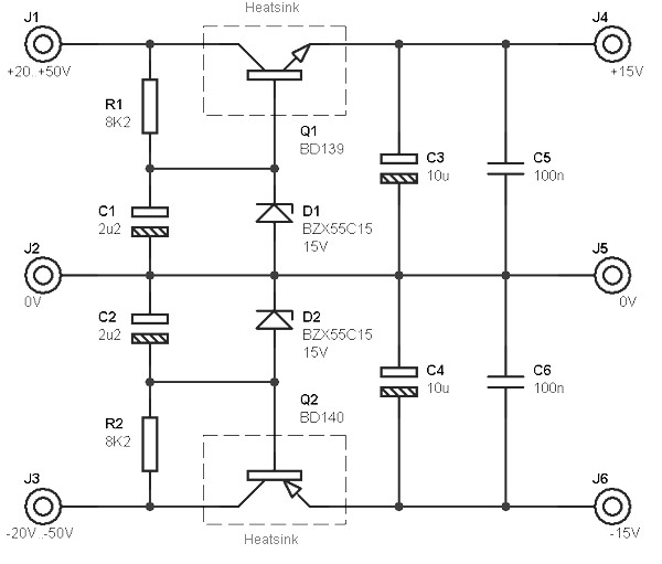
This circuit is designed to be integrated into an existing circuit, such as an audio amplifier, which already supplies symmetric voltages of +20V/-20V and +50V/-50V. The schematic diagram is derived from a dual polarity power supply circuit providing +/-...
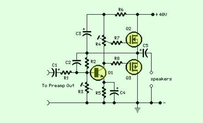
The function of this circuit is an audio amplifier capable of delivering a decent output power with a minimal number of components, with considerable efficiency. This audio amplifier circuit is designed to enhance audio signals, providing sufficient output power while...
A battery is a low-impedance power source. It operates most efficiently and economically when providing low voltage at high current. Batteries serve as essential components in various electronic circuits, functioning as a reliable source of energy. Their low-impedance characteristic allows...
This project originates from the past and has demonstrated significant success. It serves as the foundation for an 8-channel proportional R/C (AM) and 145MHz FM chat box. The receiver design is straightforward and includes a single transistor mixer followed...