
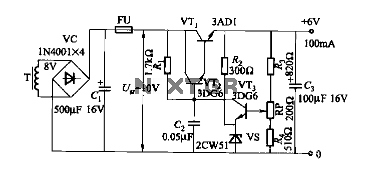
Composite tube transistors stabilized power supply circuit
Composite pipes are often utilized in various applications due to their lightweight, strength, and flexibility. When discussing the reduction of a composite pipe, it is essential to understand the implications for the control current within the system. The reduction of the pipe's diameter can lead to changes in flow dynamics, which may affect the resistance and impedance characteristics of the circuit.
In electronic applications where composite pipes are employed, such as in fluid control systems or cooling systems for electronic components, the control current can be adjusted by modifying the pipe's dimensions. This adjustment can be achieved through various methods, including the use of valves or variable diameter sections within the composite pipe. By reducing the diameter, the velocity of the fluid may increase, which can impact the thermal management and the overall efficiency of the system.
Furthermore, in circuits where sensors or actuators are integrated, the control current adjustment can lead to enhanced responsiveness and precision in the system's operation. The design of the composite pipe must account for the materials used, their thermal properties, and their compatibility with the fluids being transported. Proper analysis and simulation may be necessary to ensure that the adjustments do not lead to undesirable effects, such as cavitation or excessive pressure drops.
Overall, the reduction of a composite pipe serves as a critical factor in optimizing control current and enhancing the performance of electronic systems that rely on fluid dynamics.Composite pipe can be reduced to promote the adjustment of the control current of the tube.
Related Circuits
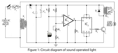
This is a hobby circuit designed for electronics enthusiasts that can turn on and off devices such as lights, fans, and radios in response to the sound of a clap. The sound is detected by a small microphone, which...
The schematic diagram below illustrates a basic sample-and-hold circuit utilizing the CA3140 as the readout amplifier for the memory capacitor. The CA3080A is also employed in the design. The sample-and-hold circuit is a crucial component in analog-to-digital conversion systems, allowing...
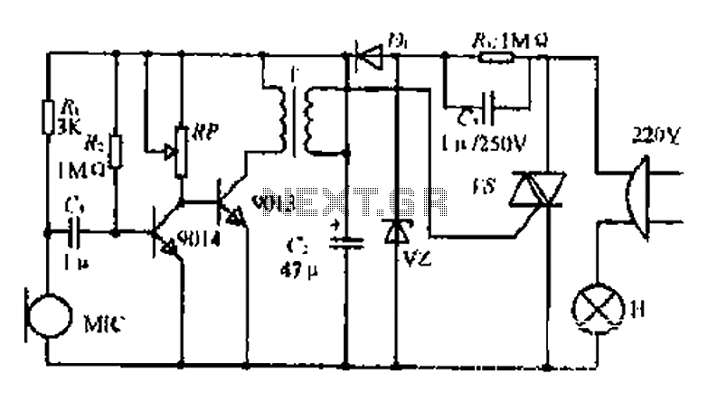
22W by Ct and R, RC Buck, rectified by n. c, filtering. vz 3V DC regulated output power, before U, V2 and MIC power supply. When the audio signal reaches the beam, the microphone MI converts acoustic energy into...
The circuit contributes 3.2 nV/√Hz of voltage noise and 0.45 pA/√Hz of current noise. To minimize noise from other sources, resistor R3 is configured to 100 ohms, resulting in an additional voltage noise of only 1.3 nV/√Hz. Resistors R1,...
PC parallel port can be very useful I/O channel for connecting your own circuits to PC. The PC's parallel port can be used to perform some very amusing hardware interfacing experiments. The port is very easy to use when...
A schematic diagram for a broadband QRP SWR metering circuit intended for use in a QRP antenna tuner. The circuit allows the user to press a momentary DPDT switch to observe an LED indicator while adjusting the capacitors of...
Warning: include(partials/cookie-banner.php): Failed to open stream: Permission denied in /var/www/html/nextgr/view-circuit.php on line 713
Warning: include(): Failed opening 'partials/cookie-banner.php' for inclusion (include_path='.:/usr/share/php') in /var/www/html/nextgr/view-circuit.php on line 713