
Neon tube flasher
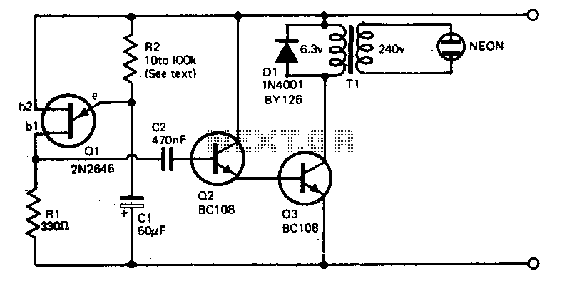
The described circuit employs a filament transformer configured in reverse to generate the necessary high voltage for igniting a neon tube. The primary side of the transformer, rated at 240 V, is connected to the unijunction transistor (Q1), which operates as a relaxation oscillator. This component generates a series of pulses that are directed to transistor Q2. Q2 acts as a switch, controlling the base current of Q3, a power transistor. When Q2 is activated by the pulses from Q1, it drives Q3 into saturation.
As Q3 saturates, it allows a significant amount of current to flow through the 6 V winding of the transformer. This rapid increase in current creates a magnetic field that induces a high voltage in the secondary winding of the transformer. The induced high voltage is sufficient to trigger the neon tube, causing it to flash.
Diode D1 is an essential protective component in this circuit. It is placed in parallel with the transformer to safeguard the transistors from voltage spikes that can occur when the current through the transformer is switched off. These spikes, if not mitigated, could damage sensitive components in the circuit. The low battery drain of 1 to 2 milliamps ensures that the circuit is energy-efficient, making it suitable for battery-powered applications. Overall, this circuit design effectively demonstrates the principles of pulse generation and transformer action in producing high voltage for neon tube operation.The voltage required to ignite the neon tube is obtained by using an ordinary filament transformer (240-6 V) in reverse. Battery drain is quite low, around 1 to 2 milliamps for a nine volt battery. The pulses from Ql, unijunction transistor, operated as a relaxation oscillator and are applied to Q2 which in turn drives Q3 into saturation.
The sharp rise in current through the 6 V winding of the transformer as Q3 goes into saturation induces a high voltage in the secondary winding causing the neon to flash The diode D1 protects the transistor from high voltage spikes generated when switching currents in the transformer. 🔗 External reference
Related Circuits
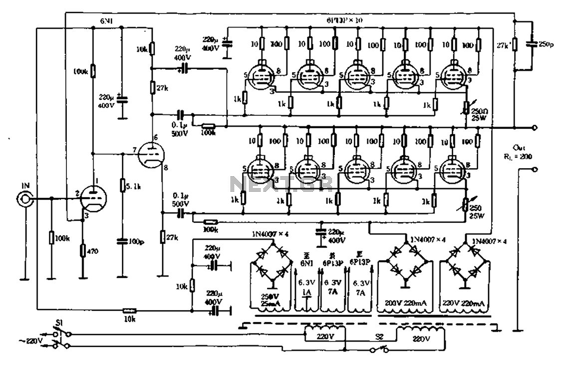
The electrical properties of a tube with a high-quality output transformer have a significant relationship, which is a well-known fact. Overseas equipment commodities have simply eliminated the so-called output transformer tube amplifier. The amplifier, as illustrated in Figures 1-31...

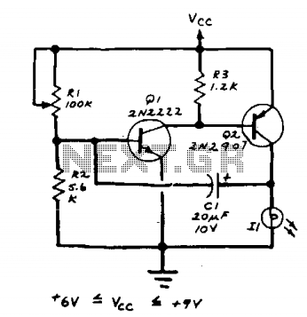
Ideal for operating 3 to 24V DC existing on-circuit lamps. This circuit was designed to provide continuous light for lamps already wired into a circuit. The circuit is intended to facilitate the operation of existing DC lamps that are integrated...
The lamp should be a No. 122, No. 222, or other similar miniature incandescent lamp. R1 adjusts the flash rate. The circuit incorporates a miniature incandescent lamp, specifically a No. 122 or No. 222 type, which serves as the primary...

Because it seemed fun to me also try the so-called "high-end tube technique to highlight here, I agree with some parts from the stock went to work. A second point was that my family had enough of my taste...
This is a simple design of a single flashlight. This small circuit is within a half hour to build. The circuit operates from 4.5 to 12 V. Of course it is possible other than to drive an LED. More:...
The LED flasher circuit operates by flashing an LED using only a 1.5-volt power supply. Typically, a power supply of more than 2 volts is required for an LED to function. The LED flasher circuit designed for operation at 1.5...