
Both tube OTL amplifier 01

The design of tube amplifiers, particularly those featuring high-quality output transformers, plays a crucial role in determining their electrical properties and overall performance. The output transformer is essential for impedance matching between the tube and the loudspeakers, facilitating optimal power transfer and enhancing audio fidelity. In the context of the amplifiers shown in Figures 1-31 and 1-32, the choice of power tubes, such as the 6P13P and 6C19, directly influences the amplifier's tonal characteristics and output power.
The 6P13P tube is known for its robust performance and is often favored in audio applications for its warm sound and dynamic range. Conversely, the 6C19 tube, which is a pentode, offers a different set of characteristics, potentially providing higher gain and a more detailed sound reproduction. The voltage amplification stage utilizing the 6N1 tube is critical, as it sets the initial gain of the amplifier and influences the overall linearity and distortion levels.
In addition to the choice of tubes, the circuit topology employed in these amplifiers is also a vital consideration. The common practice involves using a push-pull configuration to enhance efficiency and minimize distortion. The inverted voltage amplification section is designed to ensure that the output signal is phase-aligned with the input signal, allowing for accurate signal reproduction.
Audiophiles often experiment with different power tube models to tailor the amplifier's sound to their preferences. Each tube type can impart unique sonic qualities, making it essential for users to understand the implications of their choices. Additionally, the design and quality of the output transformer itself can significantly affect the amplifier's performance, as it must handle the power requirements and frequency response effectively.
Overall, the interplay between tube selection, circuit design, and output transformer quality is fundamental to achieving high-performance tube amplifiers that meet the discerning standards of audiophiles.Electrical properties of the tube with good quality output transformer has a great relationship, it is well known thing. Overseas equipment commodities have simply cancel the s o-called output transformer tube amplifier q OTI an amplifier as shown in Figure 1-31 and Figure 1-32 is such a commodity in the two countries are mouth tube products, circuit basically the same, the difference is that power tube models, Figure 1. 31 using 6P13P; Figure 1-32 using 6C19, inverted and the voltage amplification part are served with 6N1 9 t equipment as a commodity most exquisite quality, such as replacement power tube will separate a model approach for audiophile reference
Related Circuits
This is a good example preamplifier for microphones that can be used in mixing consoles. The circuit uses a dual op-amp, type NE 5532. The amplifier must be adjusted. This connect the power supply and control over P1 such...
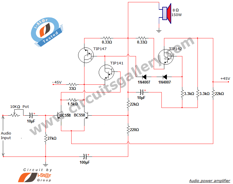
This document presents a new audio power amplifier schematic utilizing TIP darlington pair transistors. It is suitable for both home audio and car audio amplifiers. The TIP142 and TIP147 darlington pair transistors create a push-pull high-power amplifier configuration, while...
Both halves of the circuit are identical. Both inputs have a dc path to ground via the input 47k control which should be a dual log type potentiometer. The balance control is a single 47k linear potentiometer, which at...
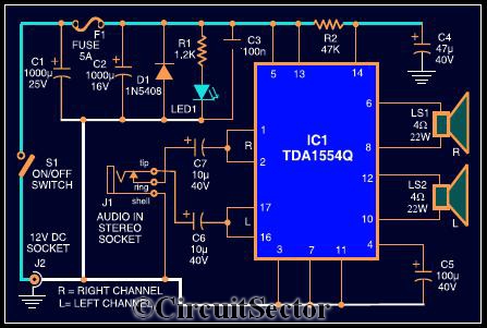
The circuit diagram illustrates a robust stereo amplifier capable of delivering 22W of power. It is based on the widely used single-chip audio power amplifier TDA1554Q (IC1), which is configured as two 22W stereo bridge amplifiers. While listening to...
The schematic diagram presented is of a twin "T" phase shift oscillator, an audio oscillator. This oscillator derives its name from the phase shift network formed by resistors R3, R4, and capacitors C1, C2, and C3. This network shifts...
The short circuit-proof outputs of amplifiers and speakers present intriguing features, including the isolation of the speakers from the amplifier output. The design of short circuit-proof outputs in amplifiers and speakers is crucial for ensuring system reliability and longevity. Such...