
new pedal schematic

The circuit utilizes a 555 timer in monostable mode, which is configured to produce a square wave output. This output is dependent on the resistor (R1) and capacitor (C1) values, which set the timing characteristics of the 555 timer. When the input signal is detected, the timer is triggered, producing a square wave that matches the frequency of the incoming note. The mixer (U2) combines this square wave with the original audio signal, allowing musicians to blend the two sounds. The potentiometers provide user control over the relative volumes of the original signal and the square wave, enabling a tailored output sound.
However, the limitation of this design lies in its fixed output frequency, which may not accurately follow the dynamic nature of the input signal. The suggestion to employ an op-amp to process the input signal before it reaches the flip-flops offers a more versatile solution. By using two flip-flops, each responding to different edges of the input waveform, the circuit can produce a more accurate representation of the input frequency, resulting in a more coherent square wave output.
In summary, this circuit design presents an innovative approach to creating a square wave accompaniment for musical notes but requires careful consideration of component values and configurations to ensure optimal performance. The proposed modifications using op-amps and flip-flops enhance the circuit's ability to track input frequencies effectively, providing a more reliable and versatile sound generation tool for musicians.U1 (555 in monostable) creates a square wave signal to matchyour signal. then it sends that square wave into the mixer (u2) along with your original signal to be mixed. so it actually is a doubler. every note you play will have a square wave note of the same pitch right beside it! the two pitches, the original and the square wave are mixable this pedal makes a note of the same pitch, in square wave. it plays along with your notes. it has 2 potentiometers in there to control how loud each is. basically, you get a square wave note and your original note Interesting circuit, but I don`t think its going to work the way you think. The output frequency will be fixed, and will be determined by the value you select for r1 and c1. Lets say you pluck the A string. That will be 110hz. You`ll trigger the 555 110 times per second, but the output will always be a set frequency. If you set r1/c1 to be to large, the output will still be cycling when the new input pulse arrives. You`ll get some staccato chirps. Here`s another way to approach this. Bring the input into an opamp, then have the opamp output go to two flip-flops. One positive edge triggered, the other negative edge triggered. Mix the two outputs using another opamp. One FF generates the positive half of the waveform, and the other FF generates the negative half. That way, you`ll track the input frquency better. Edit: Btw, I wasn`t clear there. You`ld use the dual FF circuit to generate double the input frequency. For the same frequency squarewave, you`ld just run the input into an opamp configured as a differentiator.
🔗 External reference
Related Circuits
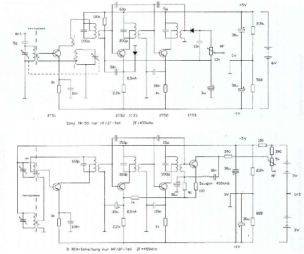
The TR-55 was the first transistor radio manufactured and sold in Japan. It utilizes the following transistors: 2T51 (oscillator-mixer), two 2T52 (for intermediate frequency), 2T53 (audio frequency driver), and 2T12. The first commercially available transistor radio was the Regency...

If you like more bass in your stereo, you can turn on a subwoofer. This is a speaker that only produces bass frequencies. Below is a circuit to ensure that the subwoofer receives only the bass frequencies. The circuit...
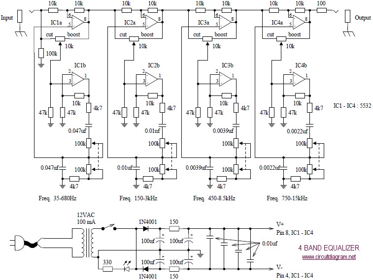
The following diagram illustrates a four-band blaster circuit. This blaster is utilized to enhance sound fidelity, emphasize specific instruments, eliminate unwanted noise, or create entirely new and distinct timbres. The four-band blaster circuit is designed to manipulate audio signals across...
This document describes a 100 Watt inverter circuit that utilizes a minimal number of components. The circuit employs the CD 4047 integrated circuit (IC) from Texas Instruments to generate 100 Hz pulses, along with four 2N3055 transistors that drive...
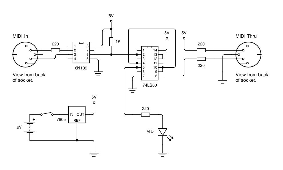
MIDI data is transmitted between instruments using a current loop, and an opto-isolator (6N139) is employed to convert this current loop into TTL pulses. The circuit utilizes the 6N139 opto-isolator to separate the MIDI signal from the receiving device, ensuring...
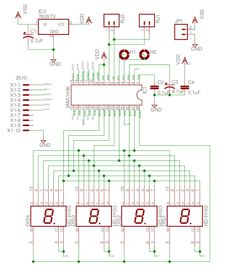
The MAX1496 is an analog-to-digital converter (ADC) that incorporates LED drivers, allowing for the construction of a 3 1/2 digit voltmeter using a minimal number of components. This device features both external and internal voltage reference options, along with...